Manufacture technology of whole 'U'-shaped silicon core

A production process and overall technology, which is applied in the production process field of the overall "U"-shaped silicon core, can solve the problems of poor contact at the lap joint, large resistance, inability to locate the silicon core in the left and right directions, and poor polysilicon quality. The effect of core lodging, first-class yield improvement, and uniform resistance

Active Publication Date: 2010-07-14
LUOYANG JINNUO MECHANICAL ENG
View PDF1 Cites 8 Cited by
  • Summary
  • Abstract
  • Description
  • Claims
  • Application Information

AI Technical Summary

Problems solved by technology

However, no matter which lap joint technology is used, the following two defects exist: 1. The contact surface at the lap joint is too small, resulting in poor contact at the lap joint and large resistance, and the quality of the polysilicon obtained here during the reduction reaction is poor. The jargon is called "turning material"; 2. During the reduction reaction process, the front and rear directions of the silicon core can be positioned by U-shaped or V-shaped grooves, but the left and right directions of the silicon core cannot be positioned. In this way, it is easy to cause the silicon core to fall during the reduction process.

Method used


Image

  • Manufacture technology of whole 'U'-shaped silicon core
  • Manufacture technology of whole 'U'-shaped silicon core
  • Manufacture technology of whole 'U'-shaped silicon core

Examples


Embodiment 1

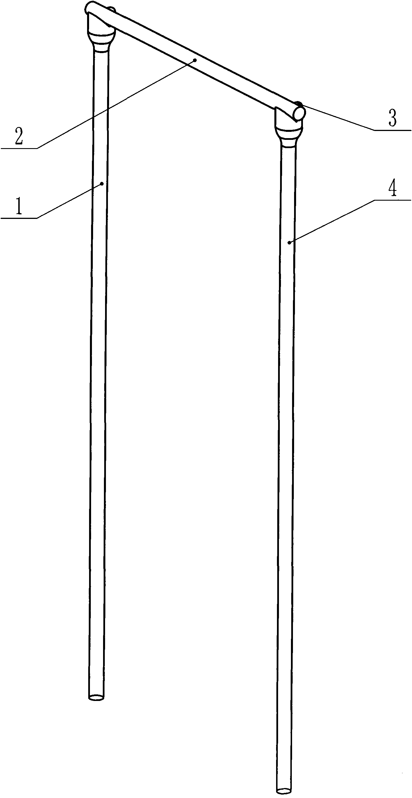
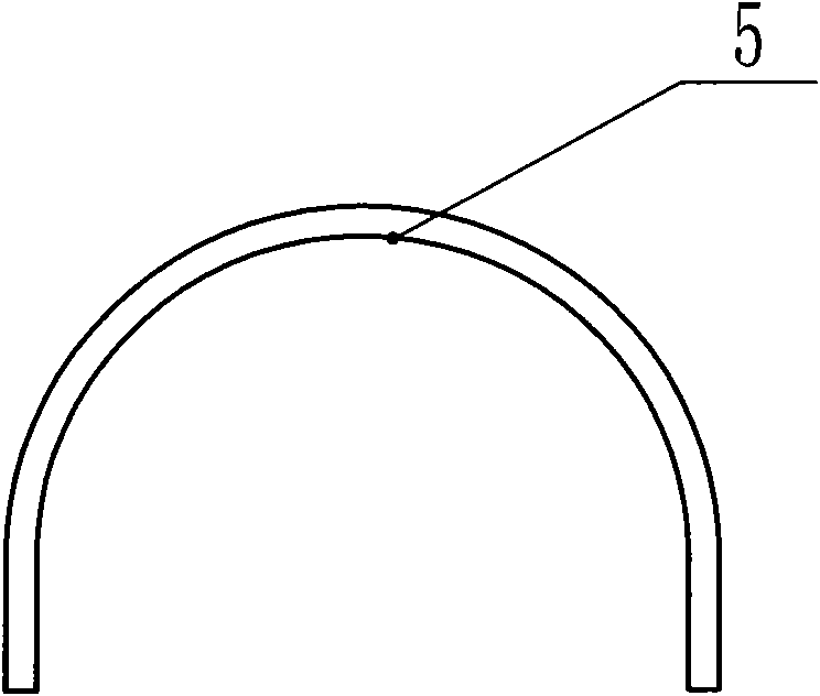
[0030] Such as Figure 4 , Figure 5 As shown, when drawing an integral "U"-shaped silicon core in a silicon core furnace, it specifically includes the following steps;

[0031] a), if figure 2 As shown, the silicon core is made into an integral "U"-shaped seed crystal 5, see patents for details (1, an integral "U"-shaped silicon core structure, application number: 200910066299; 2, a silicon core bending device And its silicon core bending method, the application number is: 200910066297) record content;

[0032] b) In a silicon core furnace in a closed argon environment, clamp an integral "U"-shaped seed crystal 5 with the upper shaft lifting system 7; the integral "U"-shaped seed crystal 5 is the patent (1. An overall "U"-shaped silicon core structure, the application number is: 200910066299; 2. A silicon core bending device and its silicon core bending method, the application number is: 200910066297), that is, the overall "U" shape The seed crystal 5 is a shorter form o...

Embodiment 2

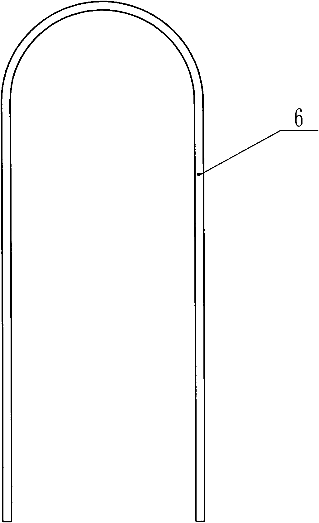
[0040] Such as Figure 6 As shown, when two integral "U"-shaped silicon cores are drawn in the silicon core furnace, the following steps are specifically included;

[0041] a), if figure 2 As shown, the silicon core is made into two integral "U"-shaped seed crystals 5, see patents for details (1, an integral "U"-shaped silicon core structure, application number: 200910066299; 2, a silicon core bending equipment And its silicon core bending method, the application number is: 200910066297) record content;

[0042] b) In a silicon core furnace in a closed hydrogen environment, clamp two integral "U"-shaped seed crystals 5 with the upper shaft lifting system 7 respectively; the integral "U"-shaped seed crystal 5 is the patent (1. An overall "U"-shaped silicon core structure, the application number is: 200910066299; 2. A silicon core bending device and its silicon core bending method, the application number is: 200910066297), that is, the overall "U" shape The seed crystal 5 is...


PUM


Abstract

The invention discloses a manufacture technology of a whole 'U'-shaped silicon core, relating to the technical field of drawing silicon core. The technology specifically comprises the following steps of: making the silicon core into a whole 'U'-shaped seed crystal, and tightly clamping the 'U'-shaped seed crystal with an upper shaft lifting system; putting a raw material stick on a material tray seat on a lower shaft lifting system, leading the raw material stick to be near to a high-frequency heating coil, and operating the high-frequency heating coil to heat the end of the raw material stick; leading the whole 'U'-shaped seed crystal to descend, and leading the vertical section of the whole 'U'-shaped seed crystal to penetrate through the inner hole of the high-frequency heating coil to be inserted into a melting zone of the raw material stick; slowly lifting up the whole 'U'-shaped seed crystal, so that the two seed crystal heads of the whole 'U'-shaped seed crystal are respectively lead molten silicon at the head of the raw material stick to be crystallized at the end of the seed crystal, and the two heads of the 'U'-shaped seed crystal are continuously drawn to be the silicon core; and stopping a furnace after the silicon core is drawn to a stated length to withdraw the 'U'-shaped silicon core. The whole 'U'-shaped silicon core drawn by the technology effectively reduces the design of a reduction furnace, the complexity of manufacture, and the unit energy consumption for manufacturing polycrystalline silicon.

Description

technical field [0001] The invention relates to the technical field of silicon core drawing, in particular to a seed crystal head which utilizes an overall "U"-shaped seed crystal to guide molten silicon to crystallize at the end of the seed crystal, and controls the overall "U"-shaped seed crystal, raw material rod The movement is finally directly drawn into the overall "U"-shaped silicon core production process. Background technique [0002] At present, in the process of producing polysilicon by the Siemens method, the technology of overlapping silicon cores is used for ordinary wafers, which is applied to a link in the production of polysilicon - the reduction reaction process; the reduction reaction is carried out in a closed reduction furnace. Before the furnace, multiple silicon cores are used in the reduction furnace to form several closed loops, which are called "bridges" in the jargon. The two vertical silicon cores of each closed loop are respectively connected to ...

Claims


Application Information

Patent Timeline
Patent Type & Authority Applications(China)
IPC IPC(8): C30B15/20C30B15/36
Inventor 刘朝轩
Owner LUOYANG JINNUO MECHANICAL ENG
Why Eureka
Try Eureka