Heat accumulating type heating furnace with smoke backflow

A regenerative, heating furnace technology, applied in lighting and heating equipment, furnaces, furnace types, etc., can solve problems such as furnace pressure fluctuation, workpiece surface oxidation, unstable working conditions, etc., to extend service life, save energy, Emission reduction effect

Inactive Publication Date: 2010-07-14
UNIV OF SCI & TECH OF CHINA
View PDF0 Cites 7 Cited by
  • Summary
  • Abstract
  • Description
  • Claims
  • Application Information

AI Technical Summary

Problems solved by technology

In the process of frequent reversing, the direction of the gas in the furnace is constantly changing, resulting in large fluctuations in the pressure in the furnace, and the working conditions are very unstable and difficult to control
[0005] (3) During the heating process, due to the direct contact between the combustion product and the workpiece, it is easy to cause oxidation and decarburization on the surface of the workpiece

Method used


Image

  • Heat accumulating type heating furnace with smoke backflow
  • Heat accumulating type heating furnace with smoke backflow
  • Heat accumulating type heating furnace with smoke backflow

Examples


Embodiment 1

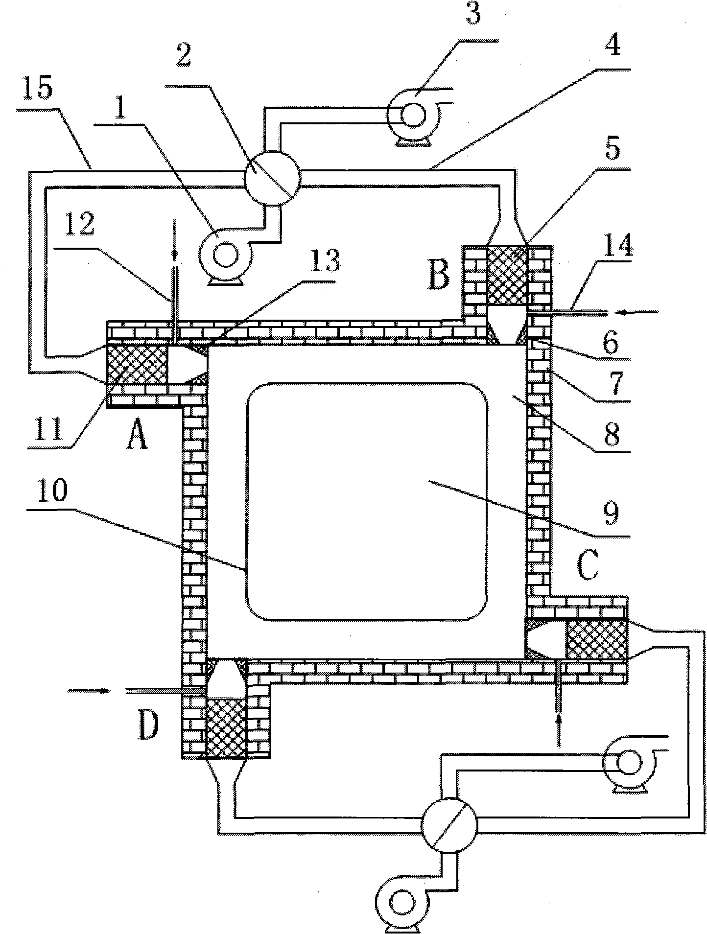
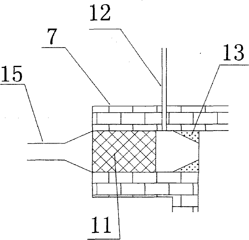
[0019] figure 1 A schematic diagram of the implementation structure of the regenerative heating furnace with flue gas reflow is given in this embodiment, including the furnace body 7, the blower 1, the induced draft fan 3 and the reversing mechanism 2, the furnace chamber 8 is rectangular or circular, and the circumferential The regenerators A, B, C, and D are arranged in the same direction. The four regenerators are divided into two groups. The two regenerators on the diagonal form a group, that is, A, C are a group, and B, D is a group of regenerators in which regenerators 11 are installed, the regenerators are spherical or honeycomb-shaped, fuel nozzles 12 are arranged downstream of the regenerators, fuel pipes are connected outside the fuel nozzles, and burner bricks are arranged on the furnace wall corresponding to the nozzles. It can be a wedge-shaped brick 13 or a special-shaped brick 16 with a guiding effect. The furnace cavity 8 and the heating chamber 9 are separated...

Embodiment 2

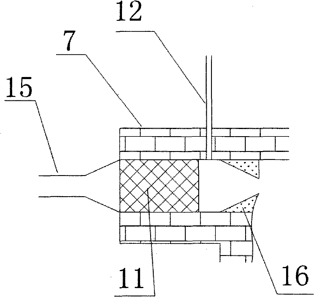
[0025] In this embodiment, the burner brick is a special-shaped brick with a guiding function.

[0026] Such as image 3 As shown, the burner brick at the nozzle of the regenerator is a special-shaped brick 16 with guiding function. Compared with ordinary wedge-shaped bricks, this special-shaped brick is more difficult to process, but it is conducive to the backflow of smoke and reduces the loss of air pressure.


PUM


Abstract

The invention provides a heat accumulating type heating furnace with smoke backflow, comprising a furnace body, regenerative chambers, a blow-off device, a fume extractor and a reversing device, wherein the furnace body is divided into a furnace cavity and a heating chamber; four corners of the furnace body are provided with four regenerative chambers in which heat accumulators are arranged; the lower course of each regenerative chamber is provided with a fuel nozzle circumscribed with a fuel pipeline; the furnace wall corresponding to the nozzle is provided with a burner block; the furnace cavity is rectangular or round; the regenerative chambers are distributed in four corners of the furnace body; the directions of nozzles are same, i.e. simultaneously clockwise or anticlockwise; the accumulator is spherical or cellular; the burner block can be arch bricks or special-shaped bricks with a guiding function; the furnace cavity and the heating chamber are separated by a refractory material with high thermal coefficient. The invention realizes the purposes of reducing carbon dioxide and nitrogen oxide emission by thermal storage and smoke backflow, separates smoke from workpieces and avoids oxidation and decarburization of workpiece surface.

Description

Technical field: [0001] The invention belongs to the technical field of combustion equipment, in particular to a regenerative heating furnace with high-temperature flue gas backflow. Background technique: [0002] In the waste heat recovery technology of the existing industrial heating furnace, the heat storage type is mainly used to recover the waste heat of the flue gas. Regenerative combustion includes heat storage system, smoke exhaust system, combustion system, etc., and each system is symmetrically arranged on both sides of the furnace body. When one side is in the smoke exhaust state, fuel and air enter from the other side, and the state is switched after a period of time. In the smoke exhaust state, the high-temperature flue gas releases heat to the regenerator, and the flue gas drops below 200°C and is discharged into the atmosphere; while on the fuel supply side, the air absorbs heat from the regenerator, mixes with fuel and enters the furnace for combustion. The...

Claims


Application Information

Patent Timeline
Patent Type & Authority Applications(China)
IPC IPC(8): F27B17/00F27D17/00F23L15/00
CPCY02E20/34
Inventor 郭超林其钊
Owner UNIV OF SCI & TECH OF CHINA
Why Eureka
Try Eureka