
Resonant converter provided with phase shift output route

A resonant converter and resonant conversion technology, applied in the direction of output power conversion device, DC power input conversion to DC power output, instruments, etc., can solve the problems of magnetic core loss, synchronous rectification, large influence, and inaccurate adjustment, etc., to achieve The effect of improving conversion efficiency and high voltage regulation accuracy

Active Publication Date: 2012-04-25
SPI ELECTRONICS
View PDF4 Cites 4 Cited by
  • Summary
  • Abstract
  • Description
  • Claims
  • Application Information

AI Technical Summary

Problems solved by technology

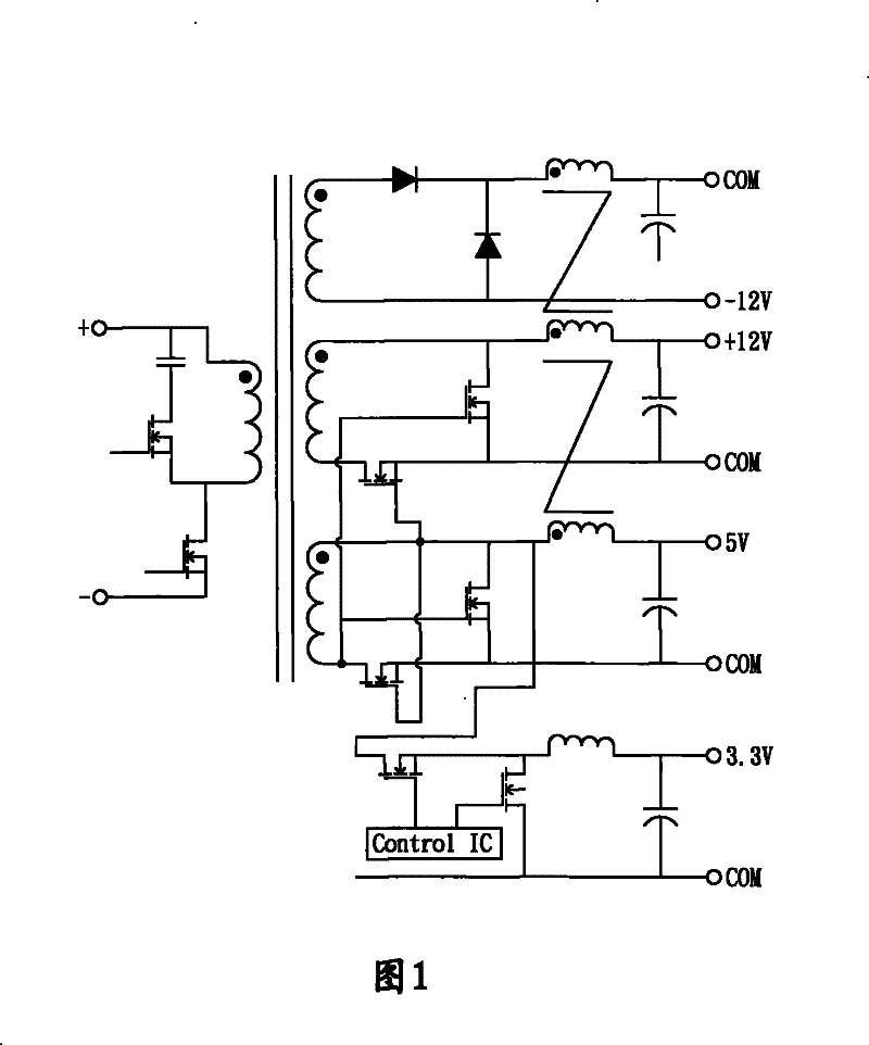
But its main disadvantages are as follows: 1. The magnetic saturation inductor has core loss and copper loss; 2. The conduction loss and reverse recovery loss of the rectifier diode; 3. The synchronous rectification of the LLC circuit is greatly affected by the magnetic saturation amplifier circuit; 4. .The inherent dead zone effect of the magnetic saturation circuit limits its operating frequency
Therefore the LLC+magnetic amplifier (magamp) circuit cannot achieve high efficiency
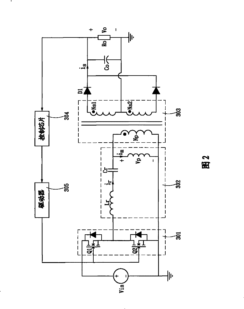
[0010] see Figure 8 As shown, LLC utilizes transformer coupling to realize multi-channel output, wherein a plurality of switching switches 301 are connected to an LLC loop 302 and a transformer 303. A coupling element 93 adjusts the duty cycle of a driver 305. The biggest problem with this architecture is the cross-regulation problem. First, the ratio of turns of the secondary side coil cannot be completely equal to the ratio of the output voltage, which will affect the regulation accuracy.
Secondly, if only the main output is controlled, the auxiliary output is only adjusted by coupling, and the accuracy is very poor, which can be improved by using weighted control, but the weighted control is to share the error between the two outputs, so that each channel cannot be adjusted accurately, so this This structure can only be used in occasions that do not require high voltage regulation
In order to improve cross-regulation, using multiple independent LLC circuits can achieve high efficiency and precise regulation, but the cost and volume are too large; if the LLC circuit is used as the main output line and the back end is connected to the main output line with a buck converter The output lines form sub-output lines, although each output line can be precisely adjusted, but the overall conversion efficiency is reduced
[0011] It can be seen that above-mentioned existing circuits obviously still have inconvenience and defects in structure and use, and need to be further improved urgently.
In order to solve the above-mentioned problems, the relevant manufacturers have tried their best to find a solution, but for a long time no suitable design has been developed, and the general product has no suitable structure to solve the above-mentioned problems. This is obviously the relevant industry. Urgent problem

Method used


Image

  • Resonant converter provided with phase shift output route
  • Resonant converter provided with phase shift output route
  • Resonant converter provided with phase shift output route

Examples


Embodiment Construction

[0057] In order to further explain the technical means and effects of the present invention to achieve the intended purpose of the invention, the specific implementation and structure of the resonant converter with phase shift output route proposed according to the present invention will be described below in conjunction with the accompanying drawings and preferred embodiments. , features and their effects are described in detail below.

[0058] The aforementioned and other technical contents, features and effects of the present invention will be clearly presented in the following detailed description of preferred embodiments with reference to the drawings. Through the description of the specific implementation mode, a more in-depth and specific understanding of the technical means and effects adopted by the present invention to achieve the intended purpose can be obtained. However, the accompanying drawings are only for reference and description, and are not used to explain th...


PUM


Abstract

The invention relates to a resonant converter provided with a phase shift output route. The resonant converter comprises a resonant conversion circuit, a switching unit, an electric power conversion circuit, a main output circuit, a resonant control unit, and at least one auxiliary output circuit, wherein the resonant conversion circuit acquires input electric power and modulates the input electric power into at least one resonant electric power; the switching unit switches the input electric power and conducts a period through the resonant conversion circuit; the electric power conversion circuit modulates the resonant electric power and outputs conversion electric power; the main output circuit is connected with the electric power conversion circuit and modulates the conversion electric power into main output electric power; the resonant control unit is electrically connected with the main output circuit to acquire a feedback signal and generate a resonant control signal, and the switching unit is driven by the resonant control signal; the at least one auxiliary output circuit is connected with the electric power conversion circuit and acquires the conversion electric power; the auxiliary output circuit is provided with a bridge type rectifying unit and a phase shift control unit; the phase shift control unit is electrically connected with the resonant control unit to acquire the resonant control signal and modulates the resonant control signal into a phase shift driving signal; and the bridge type rectifying unit is controlled by the phase shift driving signal to modulate the conversion electric power into auxiliary output electric power. Therefore, the conversion efficiency of the conventional circuit is enhanced and the deficiency of cross regulation is improved.

Description

technical field [0001] The present invention relates to a resonant converter with a phase-shift output route, a structure of a power conversion circuit, and in particular to a resonant converter with a phase-shift output route using resonance and phase-shift control technology. Background technique [0002] Nowadays, the laws and regulations of various countries have continuously improved the conversion efficiency requirements of power supplies. At present, the 80PLUS standard (standard) promulgated by Energy Star stipulates the efficiency of multi-output power supplies for computers and servers. The 80plus standard (standard ) is divided into four levels: 80plus E-star 4.0, 80plus bronze (bronze), 80plus silver (silver) and 80plus gold (gold). Among them, the 80plus gold medal (gold) requires the efficiency of the power supply to be 87%, 90% and 87% at 20%, 50% and 100% load respectively. The general structure of the current computer and server power supply is PFC+multi-ou...

Claims


Application Information

Patent Timeline
Patent Type & Authority Patents(China)
IPC IPC(8): H02M7/04H02M3/24
Inventor 南长合徐明陈桥梁
Owner SPI ELECTRONICS
Learn More