
Plasma treatment device with diffused dissociation

A plasma and processing device technology, applied in the field of plasma processing devices, can solve the problems of narrow inlet passage 200, precipitation, energy consumption, etc., and achieve the effects of accelerating processing speed, increasing density, and shortening time

Active Publication Date: 2010-07-28
ADVANCED MICRO FAB EQUIP INC CHINA
View PDF5 Cites 10 Cited by
  • Summary
  • Abstract
  • Description
  • Claims
  • Application Information

AI Technical Summary

Problems solved by technology

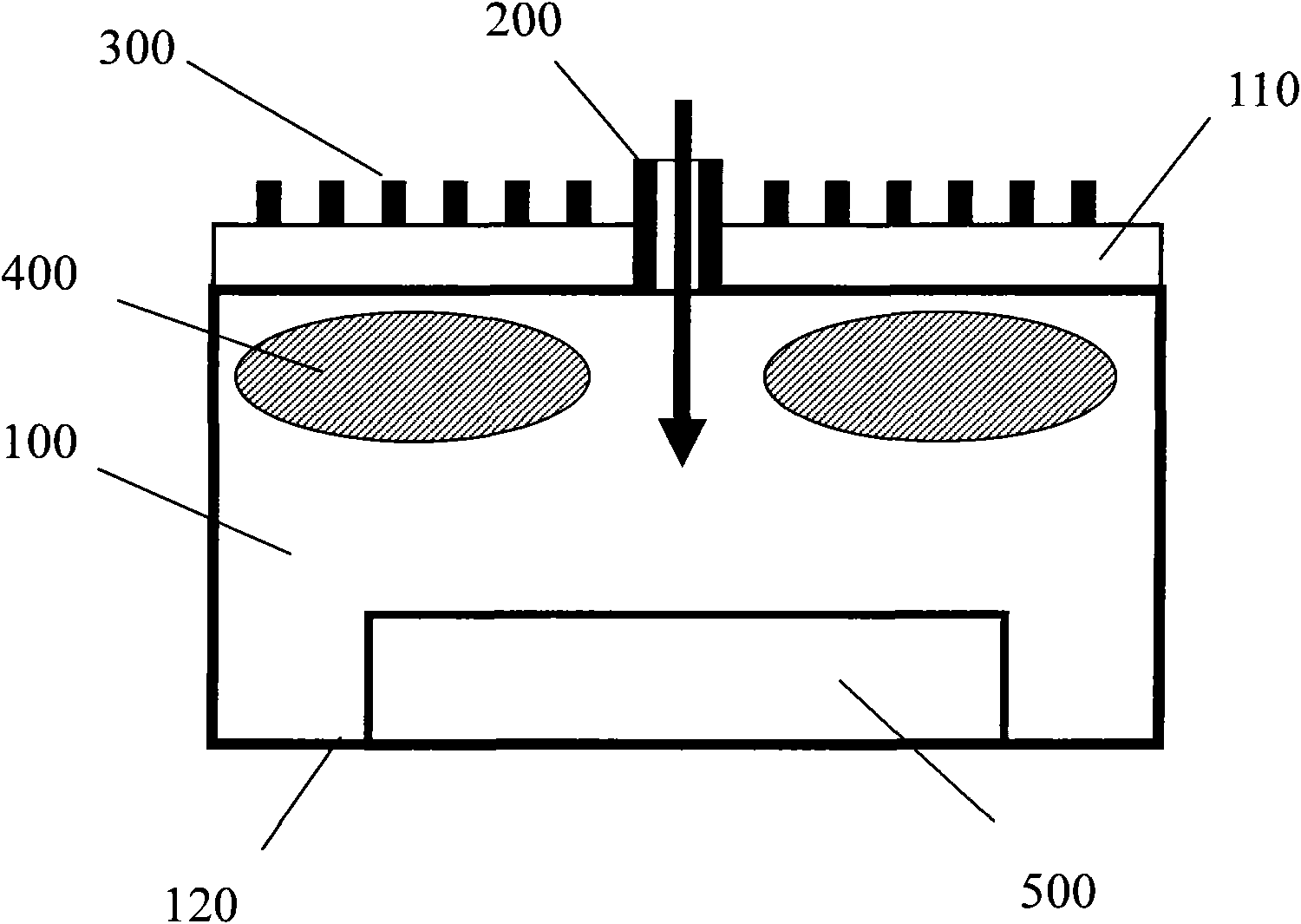
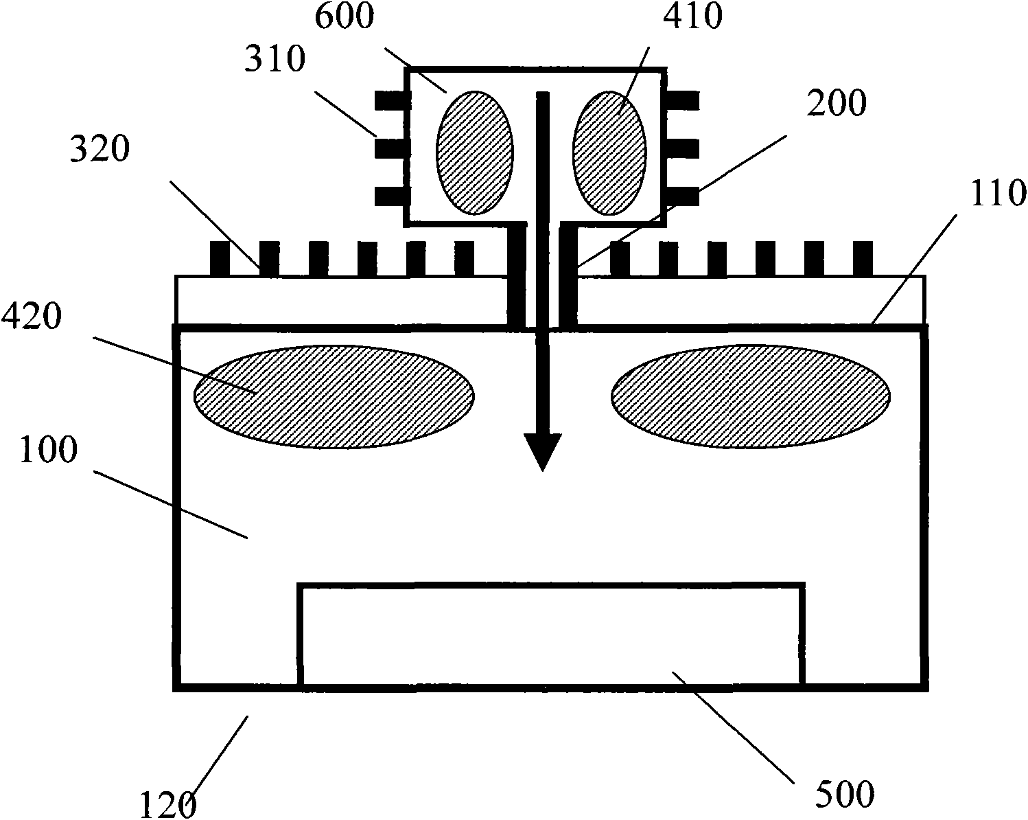
[0007] Although in this plasma processing device, the reaction gas is bombarded by high-speed electrons in the plasma generated by the alternating magnetic fields of the first coil 310 and the second coil 320 in sequence, which increases the density of free radicals, but due to the The entrance is very narrow, and the reaction gas and the inductively coupled plasma generated in the auxiliary chamber 600 cannot quickly enter the intake channel 200 and will settle at the bottom of the auxiliary chamber 600
Moreover, during the process of being introduced into the processing chamber through the inlet channel 200, many high-speed electrons, free radicals, etc. escape from the plasma and revolve with the direction of the induced electric field, collide with the narrow inlet channel 200 and adhere to it, thus consuming a large amount of energy. energy

Method used


Image

  • Plasma treatment device with diffused dissociation
  • Plasma treatment device with diffused dissociation
  • Plasma treatment device with diffused dissociation

Examples


Embodiment 1

[0037] A plasma processing device with a diffusion dissociation region provided in this embodiment is used to generate an inductively coupled plasma (ICP) introduced into the gas to react with the surface of the substrate to achieve etching of the substrate.

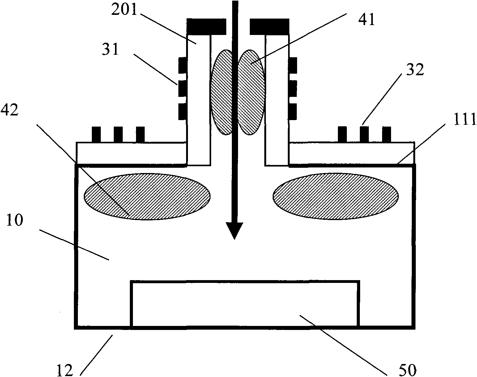
[0038] See image 3 As shown, the plasma processing apparatus includes a processing chamber 10 and an air inlet channel 201 connected through the ceiling 111 of the processing chamber 10 .

[0039] The inside of the processing chamber 10 is vacuum. A substrate 50 to be etched is placed on the bottom plate 12 of the processing chamber 10 .

[0040] The air inlet channel 201 is cylindrical, corresponding to the placement position of the substrate 50 , and vertically arranged on the top plate 111 of the processing chamber 10 . A reactive gas for etching the substrate 50 is introduced into the processing chamber 10 via the gas inlet channel 201, and the reactive gas contains oxygen O 2 or nitrogen N 2 etching gas.

[00...

Embodiment 2

[0050] See Figure 4 As shown, the overall structure of this embodiment is similar to that of the plasma processing apparatus with a diffusion dissociation region provided in Embodiment 1, and the top plate 112 of the vacuum processing chamber 10 is provided with a gas inlet corresponding to the position of the substrate. The channel 202, the first coil 31 and the second coil 32 are respectively arranged on the outside of the inlet channel 202 and the top plate 112 of the processing chamber 10, and the alternating current is respectively passed through to generate the first and second diffusion dissociation of the inductively coupled plasma region, and an induced magnetic field is generated to accelerate the electrons in the plasma, and the gas molecules in the plasma are bombarded twice to fully dissociate to obtain a plasma with a high density of free radicals.

[0051] The only difference is that the shape of the air inlet channel 202 in this embodiment is an inverted funne...

Embodiment 3

[0054] See Figure 5 As shown, the overall structure of this embodiment is similar to that of the plasma processing device with a diffusion dissociation region provided in Embodiments 1 and 2, and the top plate 113 of the vacuum processing chamber 10 is provided through the top plate 113 corresponding to the position of the substrate. The air inlet channel 203, the first coil 31 and the second coil 32 are respectively arranged outside the air inlet channel 203 and the top plate 113 of the processing chamber 10, and the alternating current is fed into the first and second diffusers of the inductively coupled plasma respectively. Dissociate the region, and generate an induced magnetic field to accelerate the electrons in the plasma, and bombard the gas molecules in the plasma twice, so as to fully dissociate to obtain a plasma with high free radical density.

[0055] The only difference is that in this embodiment, the air inlet channel 203 is trumpet-shaped with a narrow top and...


PUM


Abstract

The invention relates to a plasma treatment device with a diffused dissociation areas, which is used for reacting inductive coupling plasmas for generating an introducing gas with a substrate. The plasma treatment device is characterized by comprising a vacuum treatment chamber, air inlet passages, first coils, first diffused dissociation areas and second coils, wherein the air inlet passages are arranged above top plates of the vacuum treatment chamber and are communicated and connected with the vacuum treatment chamber; the first coils are arranged on the air inlet passages; the first diffused dissociation areas are arranged inside the air inlet passages which are provided with the inductive coupling plasmas for generating the introducing gas; and the second coils are arranged on the top plates of the treatment chamber, since the first coils and the second coils are arranged, gas molecules of the plasma are subjected to electronic bombardment for two times in the first diffused dissociation areas and the second diffused dissociation areas in sequence and then fully dissociated; in addition, the vertical through air inlet pipeline is widened and lengthened, the bottom of the vertical through air inlet pipeline is set into an inverse funnel or a horn shape and the vertical through air inlet pipeline corresponds to the substrate, so that the plasma dissociated by the bombardment can be quickly introduced to the surface of the substrate; and the density uniformity of the plasma on the surface of the substrate can be improved to shorten the time of treating reaction.

Description

technical field [0001] The invention relates to a plasma processing device, in particular to a plasma processing device with a diffusion dissociation area. Background technique [0002] At present, in the manufacturing process of semiconductor devices, etc., the commonly used inductively coupled plasma (ICP) processing device is used to generate the inductively coupled plasma of the introduced gas to react with the surface of the semiconductor device, and realize the processing technology such as etching of the semiconductor device. . [0003] See figure 1 As shown, in the existing inductively coupled plasma processing device, the reaction gas is introduced from the gas inlet channel 200 provided on the upper part of the vacuum processing chamber 100 . The coil 300 arranged outside the top plate 110 of the vacuum processing chamber 100 generates an alternating induced magnetic field after passing through the alternating current, so that the diffusion and dissociation of th...

Claims


Application Information

Patent Timeline
Patent Type & Authority Applications(China)
IPC IPC(8): H01J37/32
Inventor 倪图强
Owner ADVANCED MICRO FAB EQUIP INC CHINA
Learn More