
Installation structure of optical fiber sensor used for contact temperature detection of power switch cabinet

A fiber optic sensor and fiber optic sensing technology, which is applied in substation/switch layout details, thermometers, measuring devices, etc., can solve the shortcomings of being susceptible to electromagnetic interference and other problems, and achieve the effects of being less susceptible to electromagnetic interference, easy to system integration, and small in size

Inactive Publication Date: 2010-07-28
NANJING PUTIAN TELECOMMUNICATIONS CO LTD
View PDF3 Cites 5 Cited by
  • Summary
  • Abstract
  • Description
  • Claims
  • Application Information

AI Technical Summary

Problems solved by technology

At present, there are wireless temperature monitoring and infrared temperature monitoring in the market. Their shortcomings are susceptible to electromagnetic interference and require power supply.
Such as charged thermocouples and direct infrared radiation cannot be used on high-voltage switch cabinets.

Method used


Image

  • Installation structure of optical fiber sensor used for contact temperature detection of power switch cabinet
  • Installation structure of optical fiber sensor used for contact temperature detection of power switch cabinet
  • Installation structure of optical fiber sensor used for contact temperature detection of power switch cabinet

Examples


Embodiment Construction

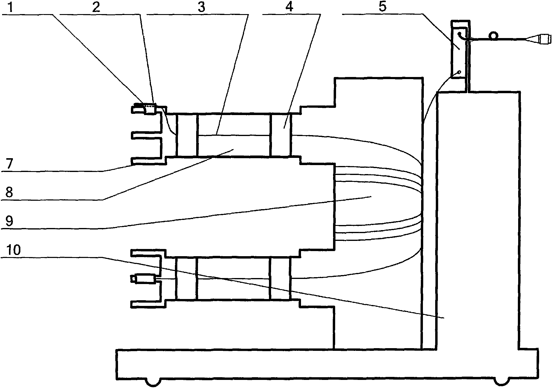
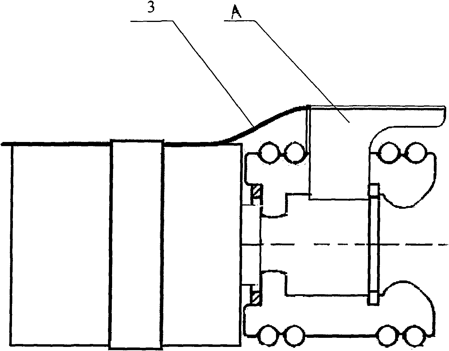
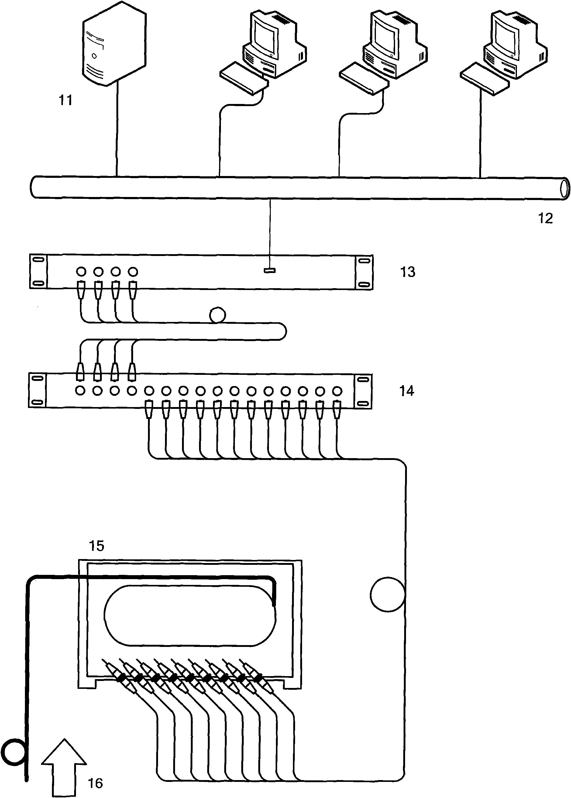
[0010] Control attached figure 1 , its structure includes sensor 1, optical fiber sensing fixture 2, sheathed optical fiber 3, heat shrinkable sleeve 4, terminal distributor 5, industrial optical fiber connector 6, circuit breaker contact 7, circuit breaker arm 8, circuit breaker A breaker column 9, a circuit breaker controller 10, wherein the sensor 1 is equipped with an optical fiber sensing fixture 2, the circuit breaker contact 7 is connected to a sheathed optical fiber 3, and a heat shrinkable sleeve 4 is provided between the circuit breaker arm 8 and the circuit breaker column 9 , the circuit breaker column 9 is connected to one terminal of the terminal distributor 5, the other terminal of the terminal distributor 5 is connected to the industrial optical fiber connector 6, and the terminal distributor 5 is connected to the circuit breaker controller 10. When working, the The optical signal representing the temperature is sent out through the optical fiber, splitter and c...


PUM


Abstract

The invention relates to an installation structure of an optical fiber sensor used for the contact temperature detection of a power switch cabinet, wherein an optical fiber sensing and fixing device is arranged on the sensor; a contact of a breaker is connected with an optical fiber with a sheath; the optical fiber with the sheath is connected with an optical fiber sensing temperature-measuring device; the optical fiber sensing temperature-measuring device is installed on a quincunx moving contact of the switch cabinet; a heat-shrinkable sleeve is arranged between an arm and an upright of the breaker; the upright of the breaker is connected with one endpoint of a terminal distributor; and the other endpoint of the terminal distributor is connected with an industrial optical fiber connector. The invention has the advantages that the installation structure is used for the optical fiber sensing temperature-measuring device, so that the installation structure has good explosion and lightning prevention and anti-electromagnetic interference capacity and can meet the insulation requirement of a power system; the installation structure has stable and reliable performance; the sensing unit has small volume and light weight; and the installation structure has the characteristics of corrosion resistance and high voltage resistance, can be used for transmitting signals in a passive way at a long distance and can be suitable for measuring the temperature in the power system and the petrochemical industry system. In addition, the installation structure can be used for monitoring the temperature of hundreds of points to be measured at real time.

Description

technical field [0001] The invention relates to an installation structure of an optical fiber sensor used for detecting the temperature of a contact of a power switch cabinet, and belongs to the technical field of optical fiber sensing and monitoring. Background technique [0002] Optical fiber sensing temperature sensing real-time monitoring technology is an effective detection method for temperature, pressure and displacement. The detection principle is to measure the variation of the internal wavelength reflection of the optical fiber with the ambient temperature, pressure and displacement, etc., to detect the external changes felt by the optical fiber sensor. Among them, temperature, pressure, displacement and flow can be measured. At present, there are wireless temperature monitoring and infrared temperature monitoring in the market. Their shortcomings are vulnerable to electromagnetic interference and require power supply. Such as charged thermocouples and direct infr...

Claims


Application Information

Patent Timeline
IPC IPC(8): H02B1/00G01K11/32G01K11/3206
Inventor 姜汉斌李想胡定宁
Owner NANJING PUTIAN TELECOMMUNICATIONS CO LTD
Learn More