Charging method and device for low pressure ceramic gas discharge tube

A gas discharge tube and gas filling device technology, which is applied in the direction of electric tube/lamp filling, etc., can solve the problems that the technical parameters of the discharge tube cannot be precisely controlled, the breakdown voltage Vs of the discharge tube varies greatly, and cannot be adjusted according to needs, etc.

Inactive Publication Date: 2010-08-04
WUXI CHAOYUAN ELECTRONICS
View PDF3 Cites 2 Cited by
  • Summary
  • Abstract
  • Description
  • Claims
  • Application Information

AI Technical Summary

Problems solved by technology

This kind of inflation method has the following disadvantages: (1) the ratio of the two mixed inert gases is generally a fixed value, which cannot be adjusted as needed, and the technical parameters of the discharge tube cannot be precisely controlled; (2) the fixed ratio stored in the steel cylinder The gas mixture in the cylinder will change with the use of time, so that the technical parameters of the discharge tube will change during the production process, especially the breakdown voltage Vs of the discharge tube will change greatly, and the quality is difficult to control; (3) The Vs value of the produced diode discharge tube is generally around 70V. For many electronic appliances, the Vs value is too high, which still poses a safety threat to electronic appliances.

Method used


Image

  • Charging method and device for low pressure ceramic gas discharge tube
  • Charging method and device for low pressure ceramic gas discharge tube
  • Charging method and device for low pressure ceramic gas discharge tube

Examples


Embodiment 1

[0027] Manufacture of low-voltage ceramic diode gas discharge tube (model 2R55Φ5.5×6). Materials are prepared as follows:

[0028] Fe-Ni-Co alloy electrode: outer diameter D=Φ5.5, neck root diameter d=Φ3.9, total height H=2.8, neck height H 1 = 2.3,;

[0029] Porcelain tube: outer diameter D = Φ5.5, inner diameter d = Φ4.0, height H = 4.95, 4 drawn carbon lines; electronic powder model: K203.5, distance between two electrodes 0.35 (the above alloy electrode and porcelain tube are Commercially available products, all in millimeters).

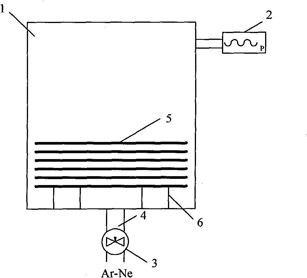
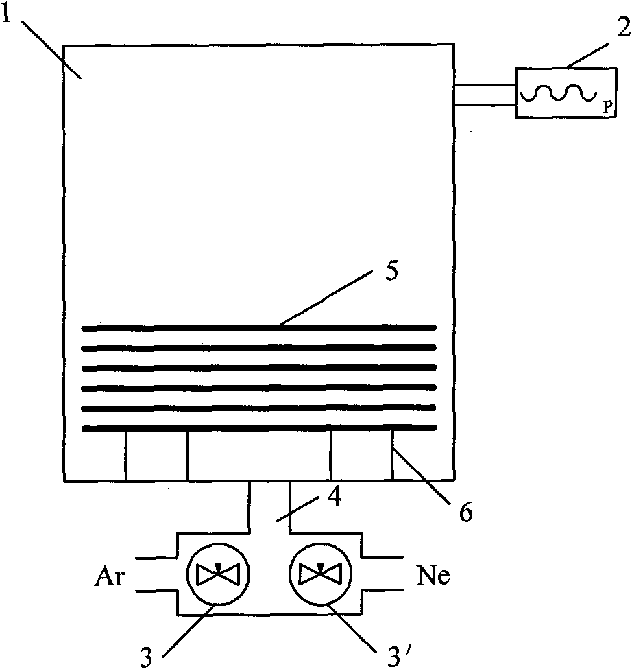
[0030] The inflation conditions are as follows: Ne-Ar mixed gas is charged, in which the number of molecules of Ar is 1.9%, and the pressure value indicated by the precision pressure gauge is -0.078MPa.

[0031] Since the initial value of the precision pressure gauge is -0.1MPa, when only Ne is charged, the Ne pressure value displayed on the precision pressure gauge 2 is calculated by the following formula: -0.078+[-0.1-(-0.078)] ×1.9%, the o...

Embodiment 2

[0039] On the basis of Example 1, only the number of molecules occupied by Ar was changed to 2.4%, and the other process conditions were unchanged, and the production was carried out. Randomly sample 14 products to test and record their Vs value. The test data is shown in the table below: (unit V)

[0040]

[0041] It can be seen from the above table that under the gas-filling conditions of Example 2, when the number of Ar molecules in the mixed gas accounts for 2.4%, a diode discharge tube with a very low DC breakdown voltage Vs can be manufactured.

Embodiment 3

[0043] On the basis of Example 2, only the serial number of the electronic powder was changed to D18K, and the other conditions remained unchanged, and the production was carried out. Randomly sample 14 products to test and record their Vs value. The test data is shown in the table below: (unit V)

[0044]

[0045] It can be seen from the above table that although the type of electronic powder has been changed compared with Example 2, a diode discharge tube with a very low DC breakdown voltage Vs can still be manufactured under the same gas filling conditions. Therefore, the inflation method of the present invention is not affected by the type of electronic powder.


PUM


Abstract

The invention discloses a charging method for a low pressure ceramic gas discharge tube, comprising the following steps of: respectively introducing two single gases with different ionization potentials into a hearth of a vacuum sealing weld furnace for mixing according to the molecule quantity; enabling the mixed gas to enter a discharge tube to be sealed and welded, which is arranged in the hearth; and finally sealing and welding an electrode with a ceramic tube of the discharge tube. The two single gases are neon gas and argon gas, wherein the molecular weight of the argon gas accounts for 1.0-2.5 percent. A charging device for the low pressure ceramic gas discharge tube comprises a heating and vacuum sealing and welding system, a precise pressure gauge connected with the heating and vacuum sealing and welding system and two parallel charging valves, wherein gas outlets of the two charging valves are respectively connected with charging ports of the heating and vacuum sealing and welding weld system. The invention enables the ratios of the two mixed gases to be adjusted according to the requirement and can realize precise control on technical parameters of the discharge tube. The low pressure ceramic gas discharge tube produced according to the mixture ratio of the two mixed gases can achieve lower direct current breakdown voltage.

Description

technical field [0001] The invention relates to the manufacturing technology of ceramic gas discharge tubes, in particular to an inflating method and an inflating device for low-voltage ceramic gas discharge tubes. Background technique [0002] The ceramic gas discharge tube is an electrical component made by sealing and welding two electrodes made of Fe-Ni-Co alloy to the two metallized ports of the ceramic tube with silver copper solder in a vacuum furnace. The tube is filled with a mixture of inert gases. The inner surface of the ceramic tube is drawn with a pencil with four carbon wires that are not connected to the metallization layer. The surface of the electrode is coated with electron powder that is conducive to the stable emission of electrons. The distance between the two electrodes and the pressure of the mixed inert gas filled in the tube can be obtained Discharge tubes of various technical properties. Ceramic gas discharge tubes are widely used in various elec...

Claims


Application Information

Patent Timeline
Patent Type & Authority Applications(China)
IPC IPC(8): H01J9/395
Inventor 李瑾枫李瑾晓
Owner WUXI CHAOYUAN ELECTRONICS
Why Eureka
Try Eureka