
Photoproduction microwave device based on double-wavelength Brillouin optical fiber laser

A fiber laser, optically generated microwave technology, applied in lasers, laser parts, phonon exciters, etc., can solve the problems of increasing the difficulty of FBG fabrication and high system cost, and achieve the effects of simple structure, low cost, and high frequency stability

Inactive Publication Date: 2010-08-04
SHANGHAI JIAO TONG UNIV
View PDF2 Cites 14 Cited by
  • Summary
  • Abstract
  • Description
  • Claims
  • Application Information

AI Technical Summary

Problems solved by technology

However, this technology has very strict requirements on the characteristics of these two FBGs, which increases the difficulty of making this FBG and also makes the system cost higher

Method used


Image

  • Photoproduction microwave device based on double-wavelength Brillouin optical fiber laser
  • Photoproduction microwave device based on double-wavelength Brillouin optical fiber laser
  • Photoproduction microwave device based on double-wavelength Brillouin optical fiber laser

Examples


Embodiment 1

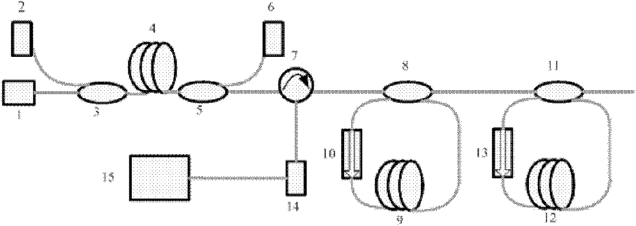
[0034] Such as figure 1 As shown, the present embodiment includes: DFB single-frequency laser 1, erbium-doped fiber amplifier, fiber circulator 7, optical resonator, cascade resonator, photodetector 14 and spectrum analyzer 15, wherein: DFB single-frequency laser 1 and The input end of the erbium-doped fiber amplifier is connected to amplify the single-frequency laser signal output by the DFB single-frequency laser 1. The output end of the erbium-doped fiber amplifier is connected to the first port of the fiber circulator 7, and its second port is connected to the optical resonator. The optical resonator is connected to the cascade resonator, the amplified single-frequency laser is input into the optical resonator and the cascade resonator in turn through the second port of the circulator 7, and the third port of the fiber circulator outputs a dual-wavelength Brillouin fiber laser The third port of the laser signal is connected to the photodetector 14 to beat the laser signal,...

Embodiment 2

[0046] The difference between this embodiment and Embodiment 1 is that: in this embodiment, the second optical fiber in the cascaded resonator is HNLF, the length of the HNLF is 253 m, and the corresponding Brillouin frequency shift is HNLF: 9.405 GHz.

[0047] The measurement resolution of the spectrum analyzer 15 is 0.1MHz.

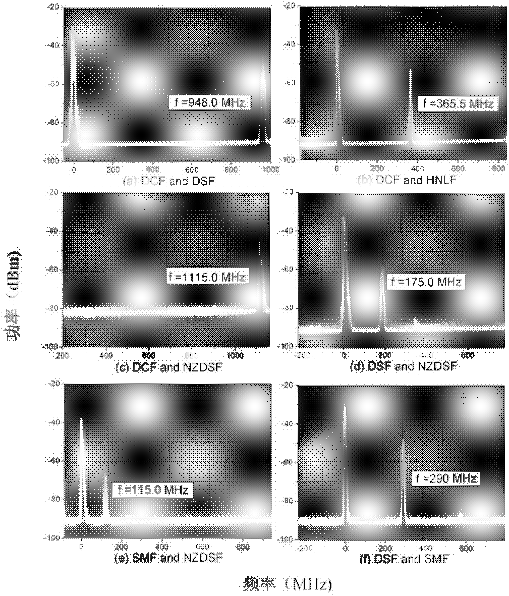
[0048] The frequency of the beat frequency microwave signal obtained in this embodiment is 365.6MHz, and its frequency spectrum is as follows image 3 (b) shown.

[0049] The schematic diagram of the frequency change of the beat frequency microwave signal obtained in this embodiment, as Figure 4 shown, from Figure 4 It can be seen that the frequency of the beat-frequency microwave signal changes with the frequency of the pump light in a very small amount, which is less than the measurement resolution of the spectrum analyzer, 0.1 MHz.

[0050] After two hours of measurement, the schematic diagram of the frequency of the beat frequency microwave sig...

Embodiment 3

[0053] The difference between this embodiment and Embodiment 1 is that the second optical fiber in the cascaded resonator in this embodiment is NZDSF, the length of the NZDSF is 350 m, and the corresponding Brillouin frequency shift is 10.895 GHz.

[0054] The frequency of the beat frequency microwave signal obtained in this embodiment is 1115.0MHz, and its frequency spectrum is as follows image 3 (c) shown.


PUM


Abstract

The invention relates to a photoproduction microwave device based on a double-wavelength Brillouin optical fiber laser in the technical field of photoelectricity, comprising a DFB (Distributed Feedback) single-frequency laser, an optical fiber amplifier, an optical fiber circulator, an optical resonant cavity, a cascade resonant cavity, a photoelectrical detector and a frequency spectrograph, wherein the cascade resonant cavity and the optical resonant cavity respectively generate single-module laser with different frequencies. The invention does not need to use an additional microwave signal source to carry out optical frequency stabilization or optical modulation, is in a full-optical fiber light path structure, and has the advantages of simple structure and low cost; and Brillouin laser generated by the two resonant cavities is generated by the same DFB single-frequency laser pumping so that the microwave signals generated by the double-wavelength Brillouin optical fiber laser at a beat frequency have high frequency stability.

Description

technical field [0001] The invention relates to a device in the field of optoelectronic technology, in particular to an optically generated microwave device based on a dual-wavelength Brillouin fiber laser. Background technique [0002] The traditional method of generating high-frequency microwave signals is mainly to realize the step-by-step frequency multiplication of low-frequency microwave signals through complex electronic circuits - electro-generated microwave technology. Although this method is relatively mature in technology, the electronic circuit system used for high-frequency microwave signal generation is relatively complicated and expensive. Moreover, in many applications, the generated microwave signal needs to be transmitted over a long distance, and if it is transmitted through ordinary coaxial cables or air, the loss is very large (the transmission loss of 60GHz microwave in the atmosphere is 14dB / km). Therefore, electro-generated microwave technology has e...

Claims


Application Information

Patent Timeline
Patent Type & Authority Applications(China)
IPC IPC(8): H01S3/30H01S3/094H01S3/10
Inventor 吴至境沈启舜詹黎袁文
Owner SHANGHAI JIAO TONG UNIV
Learn More