Automatic preamplification and precompensation twisted-pair video transmission method and system

A video transmission and twisted pair technology, applied in the field of video transmission methods and systems, can solve the problems of high engineering cost, increased use cost, and lack of precise standards for on-site debugging.

Active Publication Date: 2010-08-04
厦门ABB智能科技有限公司
View PDF8 Cites 14 Cited by
  • Summary
  • Abstract
  • Description
  • Claims
  • Application Information

AI Technical Summary

Problems solved by technology

[0005] (2) During on-site debugging, a lot of auxiliary equipment is needed, such as video signal source, display device, power supply, etc., which consumes manpower and material resources;
[0006] (3) Since there is no precise standard for on-site debugging, it is often subjectively judged whether the image is clear, it is difficult to judge whether the adjusted parameters are really suitable, and the adjustment effect is often greatly reduced;
[0008] (5) Due to the aforementioned reasons, the project cost is relatively high
[0009] Please refer again figure 2 As shown, it is the technical solution provided in Chinese Patent Application No. 02129760.6, titled "A Remote Video Image Monitoring System". In a long-distance transmission network, a repeater is added every The repeater transfers the video signal, thereby reducing the signal attenuation in the video transmission and enhancing the anti-interference performance. However, in practical application, this method has the disadvantage of inconvenient construction and installation, which increases the cost of

Method used


Image

  • Automatic preamplification and precompensation twisted-pair video transmission method and system
  • Automatic preamplification and precompensation twisted-pair video transmission method and system
  • Automatic preamplification and precompensation twisted-pair video transmission method and system

Examples


Embodiment Construction

[0035] The present invention will be described in detail below in conjunction with the accompanying drawings and specific embodiments.

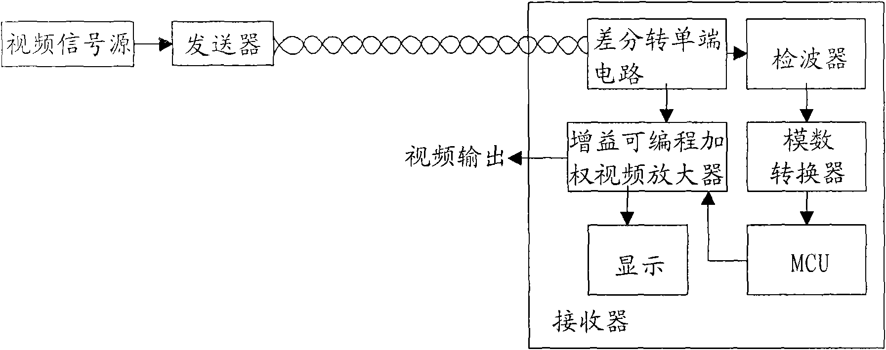
[0036] first reference Figure 10 Shown is a schematic flow chart of a twisted pair video transmission method with automatic pre-amplification and compensation of the present invention, which includes the following steps:

[0037] A twisted pair video transmission method with automatic pre-amplification and compensation, comprising the following steps:

[0038] (1) Before video signal transmission, the transmitter sends out a reference signal, and sends it to the receiver after performing minimum weighted gain on it;

[0039] (2) After the receiver receives the reference signal, it first detects the signal amplitude and compares it with the standard value. If the amplitude of the reference signal is less than the standard value, then enter step (3), otherwise enter step (6);

[0040] (3) The receiver sends a weighting instruction to the tra...


PUM


Abstract

The invention discloses an automatic preamplification and precompensation twisted-pair video transmission system. The basic structure of the system at least comprises a transmitter, two pairs of twisted pairs and a receiver, wherein the transmitter comprises at least one video input impedance matching circuit, whereas the receiver comprises at least one video output impedance matching circuit; the transmitter also comprises a multistage stepping adjustable gain video weighting amplifier, a reference signal generator, a multipath selective switch, a microprocessor and a data communication transceiver, and the receiver also comprises a signal amplitude detector, a microprocessor and a data communication transceiver, wherein the signal amplitude detector sends the amplitude of a reference signal to the microprocessor. The structure can effectively carry out automatic and accurate compensation on the loss of a video signal in twisted-pair transmission, reduce the engineering debugging difficulty and improve the capacity of resisting disturbance of video signal transmission. The invention also discloses the automatic preamplification and precompensation twisted-pair video transmission method.

Description

technical field [0001] The invention relates to the communication field, in particular to a video transmission method and system. Background technique [0002] At present, when video signals are transmitted over long distances through cables, problems such as loss of received video signals and degradation of signal-to-noise ratio often occur due to reasons such as transmission distance, physical characteristics of transmission lines, and electromagnetic interference. Various solutions have emerged for similar problems in video transmission. [0003] For example, Chinese patent application number 95115443.5, titled "Video wire and cable long-distance transmission correction system", application number 00215632.6, titled "Weighted Video Amplifier", application number 02129760.6, titled "A remote video image monitoring system", application number 200420035285.4, named "Video Universal Balanced Transmission Converter", application number 200520080801.X, named "A Weighted Anti-j...

Claims


Application Information

Patent Timeline
IPC IPC(8): H04N7/10
Inventor 周大林张仰鹏王琦谭波
Owner 厦门ABB智能科技有限公司
Why Eureka
Try Eureka