Sputtering system

A magnetron sputtering and radial technology, applied in the field of coating substrates, can solve the problems of separating the reaction zone and the deposition zone, limiting the overall number of film applications, etc.

Inactive Publication Date: 2010-08-04
KONINK PHILIPS ELECTRONICS NV
View PDF1 Cites 9 Cited by
  • Summary
  • Abstract
  • Description
  • Claims
  • Application Information

AI Technical Summary

Problems solved by technology

[0004] A disadvantage of the prior art described above is the need to physically and atmospherically separate the reaction zone from the deposition zone
This separation, for example, limits the number of targets and reaction zones that can be placed in a given vacuum chamber, thereby limiting the overall number of membrane applications

Method used


Image

  • Sputtering system
  • Sputtering system
  • Sputtering system

Examples


Embodiment Construction

[0028] The sputtering device chosen as an example is a development of the sputtering system described in EP 0 516 436 B1, the disclosure of which is hereby incorporated by reference.

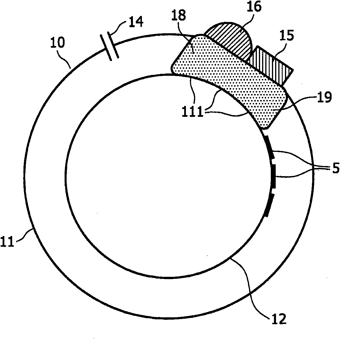
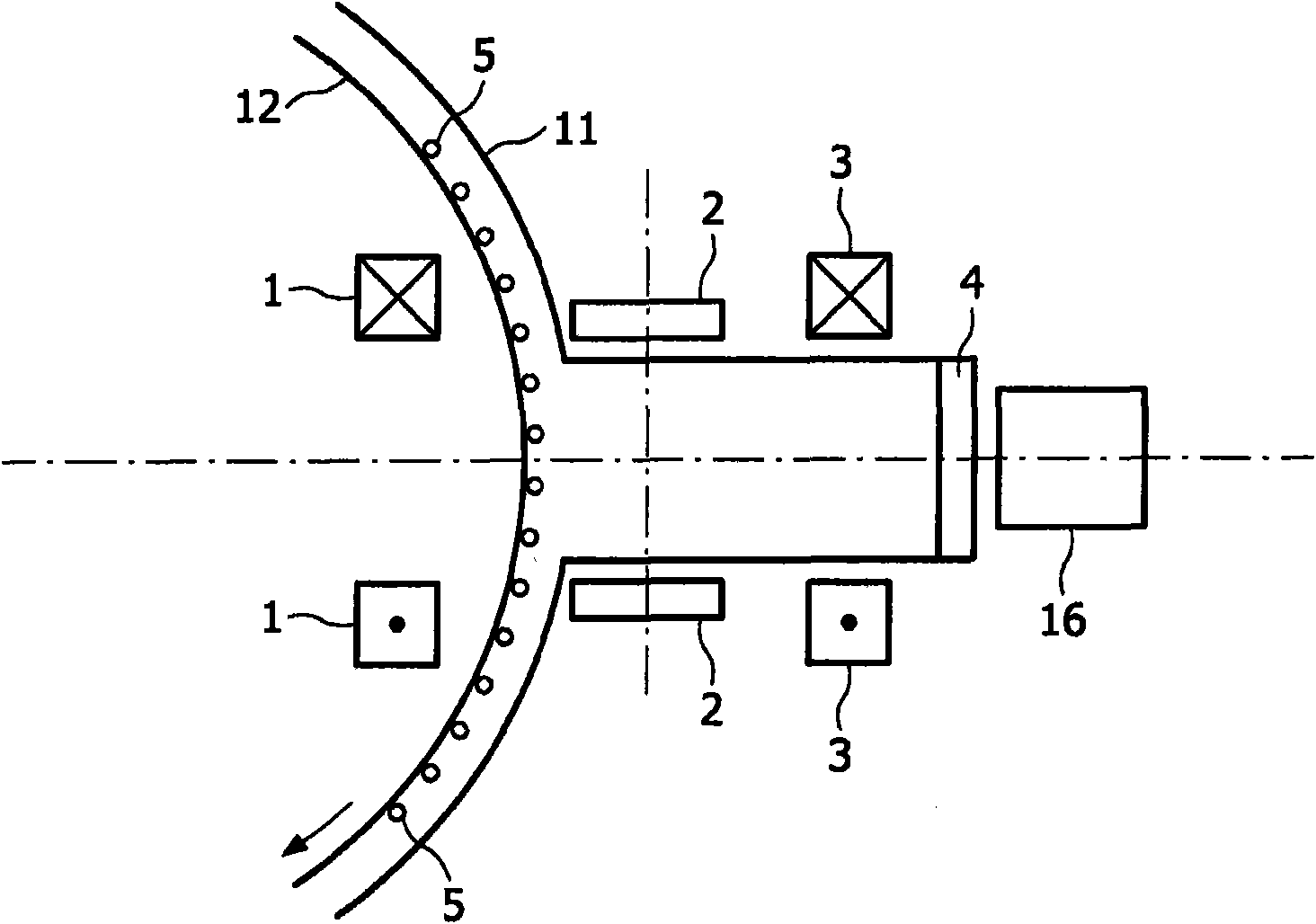
[0029] refer to figure 1 , the sputtering system 10 has a housing 11, the periphery of which forms a vacuum chamber. The housing 11 itself may be connected to a vacuum system (not shown). On the periphery of the vacuum envelope of the envelope 11 (hereinafter also designated as the chamber 11 ), a magnetron sputtering device 15 is provided, which is closely adjacent to a plasma generating device 16 . In this embodiment, the plasma generating device 16 is a microwave generator.

[0030] During operation, an inert sputtering gas (such as eg argon) is introduced in the chamber 11 through the inlet 14 . In addition, a reactive gas such as, for example, oxygen is introduced through the inlet 14 . When the substrate (which is disposed on the drum 12 ) is rotated into the region 19 of the larger pl...


PUM


Abstract

The invention relates to a device (10) for sputtering at least one selected materialonto a substrate (5) and bringing about a reaction of this material, comprising a vacuum chamber (11), in which a substrate holder (12) is arranged, at least one magnetron sputtering mechanism (15), which is arranged in a workstation close to the substrate holder (12) and which has a target of the selected material which is suitable for producing a first plasma for sputtering at least one material onto the substrate (5), as well as a secondary plasma mechanism (16) for producing a secondary plasma, which is arranged in the workstation close to the magnetron sputtering mechanism (15) and close to the substrate holder (12), the sputtering mechanism (15) and the secondary plasma mechanism (16) forming a sputtering zone and an activation zone. At least two electromagnets (1, 3) and / or radiallymagnetized toric magnets as well as at least one magnetic multipole (2), which is formed from a plurality of permanent magnets, are arranged to produce magnetic fields to include the secondary plasma. The invention also relates to a method for coating a substrate, in which firstly materialis deposited on a substrate by means of a sputtering process and the deposited materialthen reacts in a plasma, which contains the necessary reactive species, to form a compound, wherein the plasma density and the degree of ionization of the plasma are increased with the aid of magnetic fields, which are produced by at least two electromagnets (1, 3) and / or radially magnetized toric magnets as well as at least one magnetic multipole (2), which is formed from a plurality of permanent magnets.

Description

technical field [0001] The invention relates to an apparatus for sputtering at least one selected material onto a substrate and causing a reaction of this material, the apparatus comprising: a vacuum chamber in which a substrate holder is arranged; at least one magnetron sputtering a sputtering mechanism disposed in the work area proximate to the substrate holder and having a target of selected material suitable for generating a first plasma for sputtering at least one material onto the substrate; and a secondary plasma mechanism for generating a secondary plasma, which is disposed in a working area close to the magnetron sputtering mechanism and close to the substrate holder, the sputtering mechanism and the secondary plasma mechanism forming a sputtering region and the activation zone. The invention also relates to a method for coating a substrate, wherein material is first deposited on the substrate by a sputtering process, and then the deposited material is reacted in a p...

Claims


Application Information

Patent Timeline
Patent Type & Authority Applications(China)
IPC IPC(8): C23C14/34H01J37/34
CPCH01J37/32678H01J37/3408
Inventor G·亨宁杰B·孔谢K·塞尔M·拉斯克T·迪德里克
Owner KONINK PHILIPS ELECTRONICS NV
Why Eureka
Try Eureka