Soft magnetic amorphous alloy
An amorphous alloy and soft magnetic technology, applied in the direction of magnetic objects, magnetic materials, inorganic materials, etc., can solve the problems of lack of universal applicability, low saturation magnetic flux density, etc., and achieve high saturation magnetic flux density and soft magnetic properties excellent effect
- Summary
- Abstract
- Description
- Claims
- Application Information
AI Technical Summary
Problems solved by technology
Method used
Image

Examples
Embodiment 1~20
[0079] (Examples 1-20, Comparative Examples 1-8)
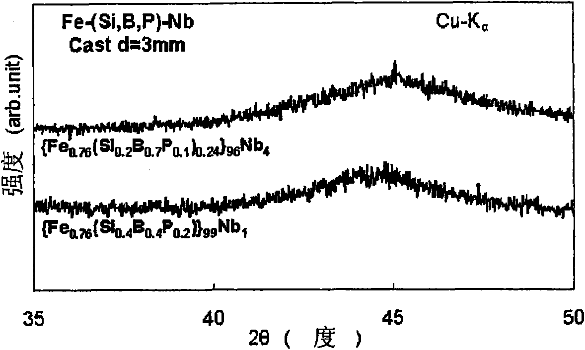
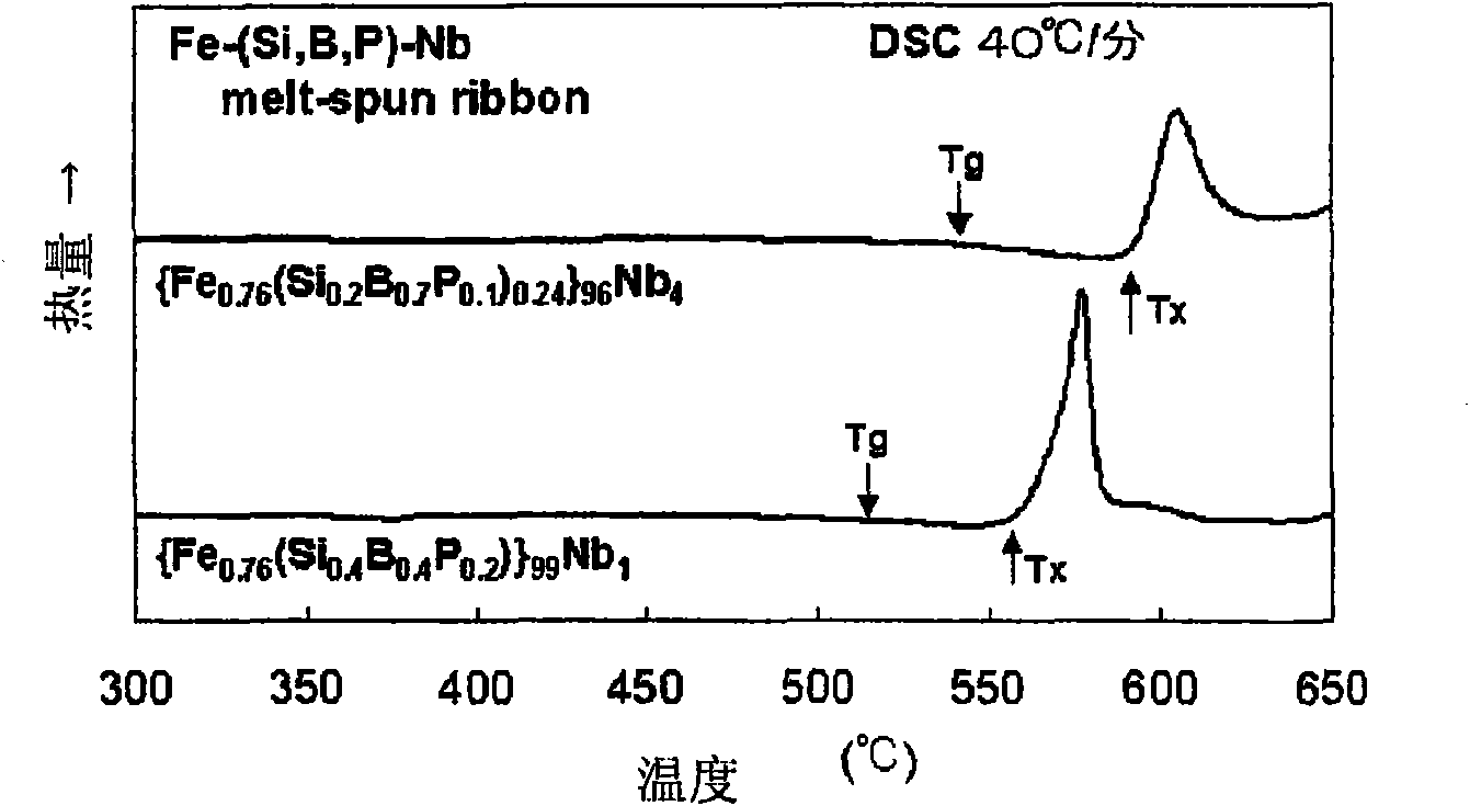
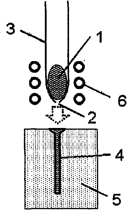
[0080] Weigh Fe, Si, B, Fe 3 Raw materials of P, Al, Cr, Zr, Nb, Mo, Hf, Ta, and W were used to prepare samples. The composition list of the samples is shown in Examples 1 to 20 and Comparative Examples 1 to 8 in Table 1. The prepared sample was placed in an alumina crucible and placed in the vacuum chamber of a high-frequency induction heating device. Next, it is evacuated, and then melted by high-frequency induction heating in a reduced pressure Ar atmosphere to produce a master alloy. The master alloy is processed by a single-roll liquid quenching method to produce a continuous ribbon. The continuous ribbon has a thickness of 20 μm, a width of about 3 mm, and a length of about 5 m. In addition, the master alloy is processed by a metal mold casting method to produce cast bars. The cast bar has a diameter of 1 to 4 mm and a length of 50 mm. Here, the cast bar is made of image 3 The device shown is made. First, a master al...
Embodiment 21~34
[0090] (Examples 21 to 34, Comparative Examples 9, 10)
[0091] Weigh Fe, Si, B, Fe 3 Raw materials of P, Al, Cr, Zr, Nb, Mo, Hf, Ta, and W were used to prepare samples. The composition list of the samples is shown in Examples 21 to 34 and Comparative Examples 9 and 10 in Table 2. Next, a master alloy was produced according to the same method as in Examples 1-20 and Comparative Examples 1-8. The master alloy was processed by a single-roll liquid quenching method to produce a continuous thin ribbon. The continuous thin strip has a width of about 10 mm, a thickness of 30 μm, and a length of about 2 m. Next, the phases of these thin ribbon surfaces were determined by X-ray diffraction, and for the thin ribbons that could be confirmed as an amorphous phase, the saturation magnetic flux density Bs was evaluated using a vibrating sample magnetometer (VSM). Next, a constant temperature and high humidity test of the thin strip was performed. Specifically, it is to cut a thin strip of...
Embodiment 35
[0098] Weigh the raw materials of Fe, Si, B, Fe3P and Nb to prepare samples. The composition of the sample satisfies {Fe 0.76 (Si x B y P z ) 0.24 } 98 Nb 2 . However, the values of x, y, and z are adjusted to Figure 4 Shows such values. In addition, as a comparative example, it is weighed to become Fe 78 Si 9 B 13 Alloy composition, make samples. Next, according to the same method as in Examples 1 to 20 and Comparative Examples 1 to 8, master alloys were produced, respectively. The master alloy was processed by a single-roll liquid quenching method to produce a continuous thin ribbon. The continuous ribbon has a width of about 5 mm, a thickness of 20 μm, and a length of about 20 m. The thin strip was then made into a wound core with an inner diameter of 14 mm and an outer diameter of 20 mm. Among them, for the wound magnetic core with the supercooled liquid region, a heat treatment is performed for 5 minutes at a temperature lower than the glass transition temperature b...
PUM
| Property | Measurement | Unit |
|---|---|---|
| particle size | aaaaa | aaaaa |
| thickness | aaaaa | aaaaa |
| thickness | aaaaa | aaaaa |
Abstract
Description
Claims
Application Information
 - R&D
- Intellectual Property
- Life Sciences
- Materials
- Tech Scout
- Unparalleled Data Quality
- Higher Quality Content
- 60% Fewer Hallucinations
Browse by: Latest US Patents, China's latest patents, Technical Efficacy Thesaurus, Application Domain, Technology Topic, Popular Technical Reports.
© 2025 PatSnap. All rights reserved.Legal|Privacy policy|Modern Slavery Act Transparency Statement|Sitemap|About US| Contact US: help@patsnap.com