Method and device for flotation by adopting spiral rotor and application

A flotation device and spiral technology, applied in flotation, solid separation, etc., can solve the problems of reduced target particle concentration of incoming ore pulp, misleading flotation equipment manufacturing industry, and low gas-liquid mixing efficiency, so as to achieve smooth flow into the tank Performance improvement, volume reduction, and service life extension

Inactive Publication Date: 2013-06-05
XINGMIN TECH ZHUZHOU
View PDF3 Cites 0 Cited by
  • Summary
  • Abstract
  • Description
  • Claims
  • Application Information

AI Technical Summary

Problems solved by technology

[0010] 1) Part of the outflow pulp returns to the floating device to form a "one-pot cooking" of the outflow pulp and the inflow pulp, resulting in a reduction in the processing capacity of the inflow pulp and the concentration of target particles, which in turn leads to a decrease in flotation efficiency
[0011] 2) The gas-liquid mixing efficiency of the floating device is low
As the mineral resource deposit form tends to be poorer in grade and complex in composition, the proportion of mineral resources in small and medium-sized reserves continues to rise, and the flotation cells dominated by previous flotation methods are getting bigger and bigger, which is misleading the manufacture of flotation equipment. The industry is blindly developing in the direction of large-scale

Method used


Image

  • Method and device for flotation by adopting spiral rotor and application
  • Method and device for flotation by adopting spiral rotor and application

Examples


Embodiment 1

[0042] Embodiment 1: A helical rotor floating device

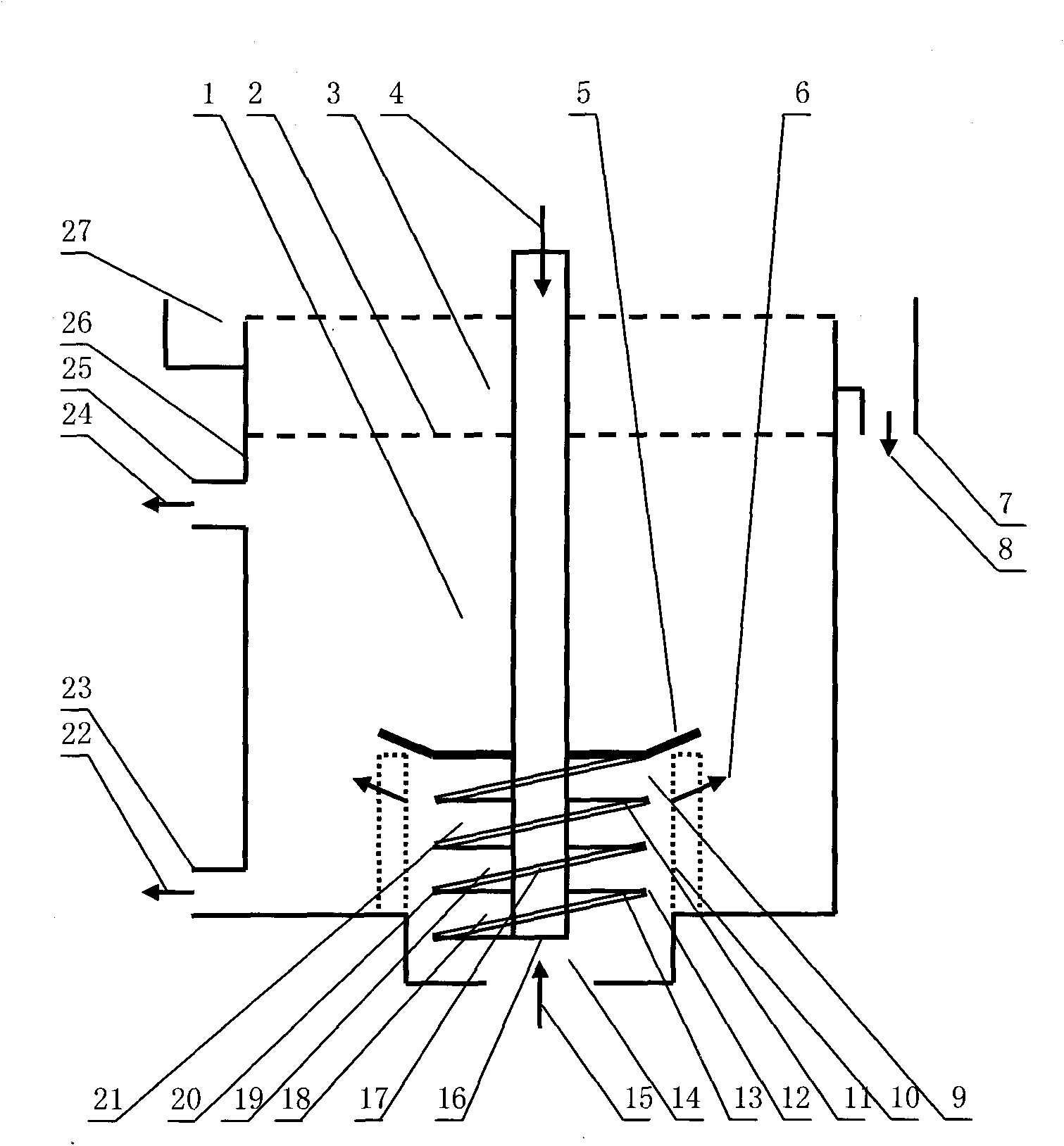
[0043] figure 1 The flotation cell shown uses a helical rotor floatation device. The floating device 9 is arranged in the lower central area of ​​the flotation cell body 26 and includes a helical rotor 11 and a stator 10 . The stator 10 is a conventional stator. The screw rotor 11 consists of screw blades 12 and a hollow rotor shaft 16 . Wherein, the number (or the number of heads) of the spiral blade 12 is 1; the diameter is 300mm; the pitch is 50mm; the thickness of the hollow interlayer is 2mm; the air holes 13 on the top surface of the blade are 1mm in diameter, and are arranged in N rows×M radial arrangement in each row; The top is provided with a dish-shaped rotor top cover 5 with an outer diameter of 400mm; the air holes 13 of the end blades are built-in air holes formed by tubular passages in the hollow interlayer. The hollow rotor shaft 16 is a shaft section wrapped by the helical blades 12, and the hollow sha...

Embodiment 2

[0046] Embodiment 2: Another helical rotor floating device

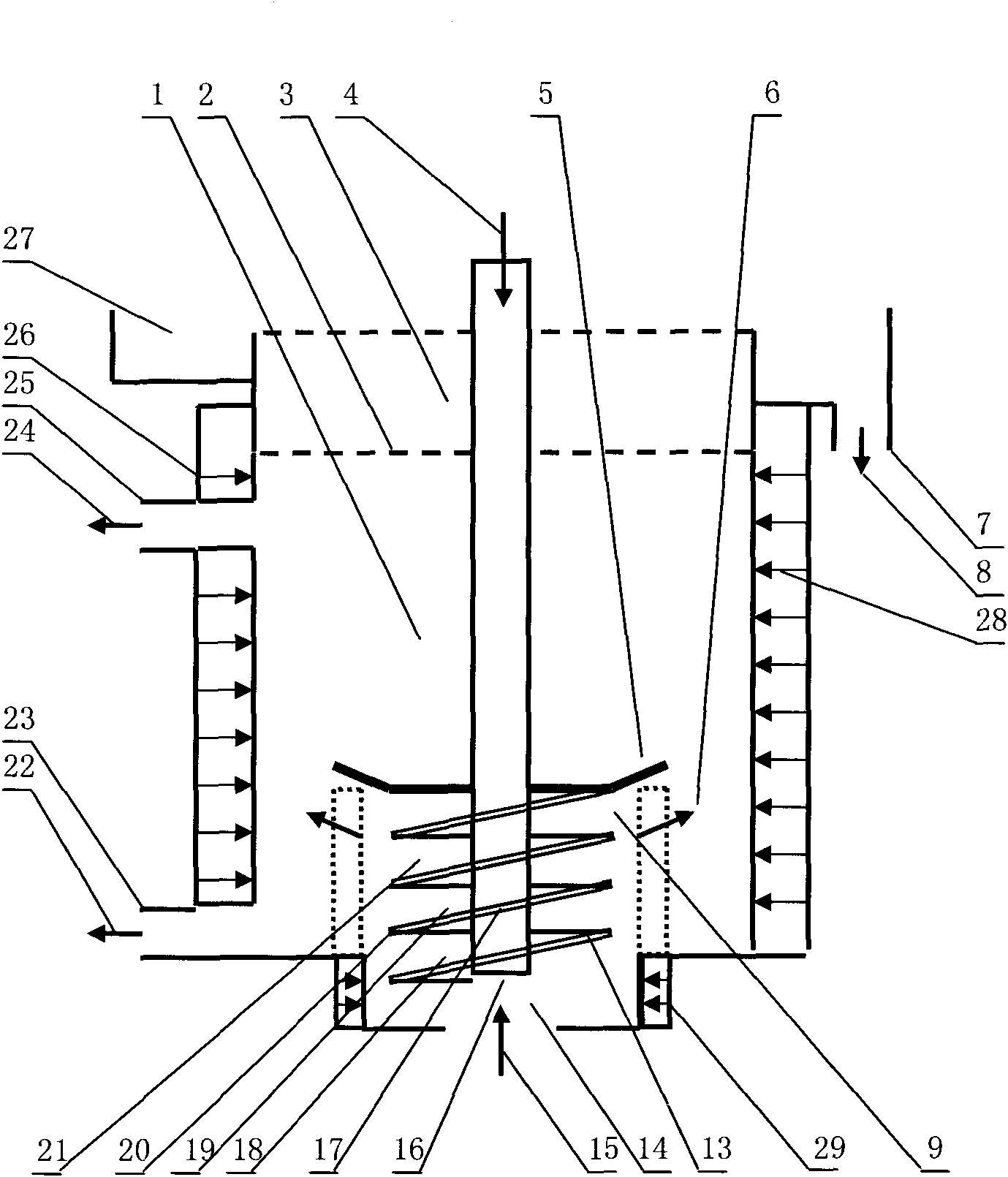
[0047] figure 2 The flotation cell shown is an improved structure of the first embodiment, the basic structure is the same as that of the first embodiment, and a helical rotor floating device is used. The floating device 9 is arranged in the lower central area of ​​the flotation cell body 26 and includes a helical rotor 11 and a stator 10 . It is characterized in that: an ultrasonic device 29 is provided at the entrance of the floating device, the ultrasonic device 29 and the flotation tank body 26 are of an integrated structure, and the ultrasonic frequency is 20kHz-1×10 6 kHz, sound intensity 0.5-200w / cm 2 . The inflowing pulp 15 enters the floating device 9 after applying ultrasonic energy by the ultrasonic device 29 .

[0048] The working principle of the present invention is: when the inflowing pulp 15 enters the ultrasonic device 29 through the inflowing pulp inlet 14, due to the effect of the set ultrason...

Embodiment 3

[0050] Embodiment 3: Another helical rotor floating device

[0051] from figure 2 It can be seen that the ultrasonic device 29 can also be arranged in a split type. When the ultrasonic treatment of the inflowing pulp 15 takes a long time, such as 1-2 minutes, it is more advantageous to install the ultrasonic device 29 in a separate manner.

[0052] The inventor has found in the course of research that some minerals (such as quartz-type gold ore, differentiated type silicate gold ore) can obtain a very high target particle recovery rate by adopting the helical rotor floating device; some minerals (such as Ultra-fine particle type gold ore, high mud type low-grade zinc oxide ore) adopts conventional flotation method, the target particle recovery rate is very low, and in the case of using the screw rotor floating device, the set ultrasonic energy treatment is applied to the inflow ore pulp 1-30 seconds, can significantly increase the recovery rate of target particles, and grea...


PUM


Abstract

The invention discloses a method for flotation by adopting a spiral rotor, which is characterized in that a floating device is provided with the spiral rotor which rotates to generate a spiral gas field; inflow ore pulp undergoes gas-liquid mixing with the spiral gas field over one time in the process of flowing through a spiral channel; and outflow ore pulp flows out of the floating device in anirreversible flow way. The spiral rotor is provided with a hollow rotor shaft in a vertical central region; at least one spiral blade is arranged on the outer surface of a lower shaft of the hollow rotor shaft; a rotor top cover is arranged on the top of the spiral blade; a hollow shaft cavity of the hollow rotor shaft is filled with compressed air; and the compressed air in the hollow rotor shaft enters into the abdominal cavity of the spiral blade through a rotor shaft air hole, is outwards ejected through a blade air hole and forms the spiral gas field inside and outside the spiral channel. The method and the device for flotation are applied to the flotation process of all solid materials which at least comprise non-ferrous ore, ferrous metal ore and nonmetallic ore, and particularly lean ore and complex and difficultly selected ore.

Description

Technical field [0001] The invention relates to a mineral flotation method, device and application, in particular to a flotation method, device and application using a helical rotor, belonging to the technical field of flotation. Background technique [0002] In the well-known flotation method, the bubble mineralization process is mainly completed during the floating process of the bubbles, that is, it is completed in the separation area of ​​the outflow pulp, and the part of the outflow pulp returns to the floating device to mix and float with the inflow pulp. The functional goal of the floating device is to generate air bubbles and complete the initial mineralization process of the air bubbles. More representative patents include: [0003] No. 4078026 U.S. Patent proposes a kind of floating device, and its rotor has independent ore slurry passage and gas passage respectively. The main idea of ​​this structure is to allow the rotor to generate dynamic pressure to compensa...

Claims


Application Information

Patent Timeline
Patent Type & Authority Patents(China)
IPC IPC(8): B03D1/00B03D1/16
Inventor 曾兴民
Owner XINGMIN TECH ZHUZHOU
Why Eureka
Try Eureka