
Method for manufacturing front side grid line electrode of solar battery

A technology of solar cells and front grid lines, which is applied in the manufacture of circuits, electrical components, and final products, and can solve problems such as degradation of battery performance, damage to solar cell substrates, and impact on conversion efficiency

Inactive Publication Date: 2010-08-18
浙江日兆新能源开发有限公司
View PDF4 Cites 16 Cited by
  • Summary
  • Abstract
  • Description
  • Claims
  • Application Information

AI Technical Summary

Problems solved by technology

However, the grooving process will cause damage to the solar cell substrate, which will reduce the performance of the cell and affect the conversion efficiency.

Method used


Image

  • Method for manufacturing front side grid line electrode of solar battery
  • Method for manufacturing front side grid line electrode of solar battery
  • Method for manufacturing front side grid line electrode of solar battery

Examples


Embodiment 1

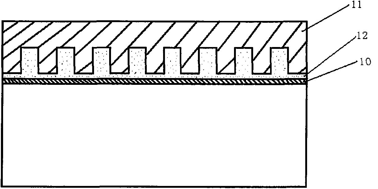
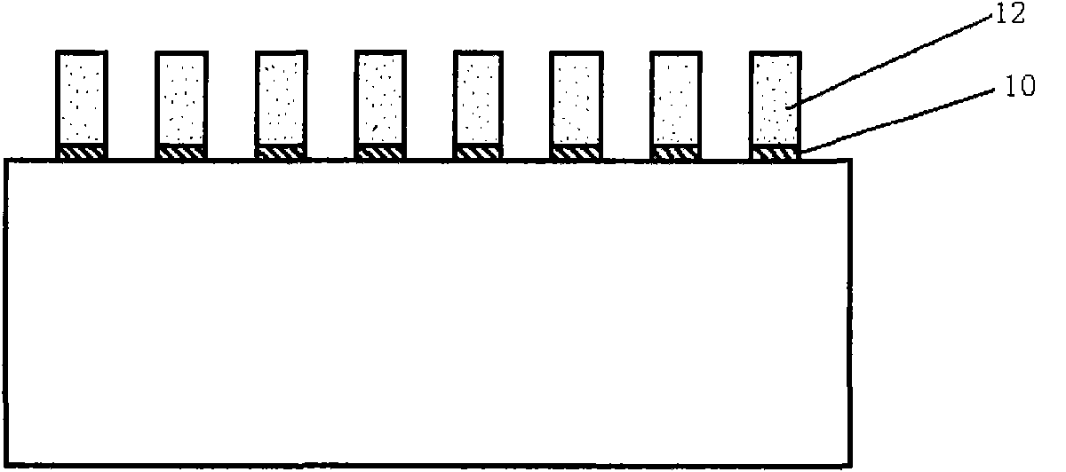
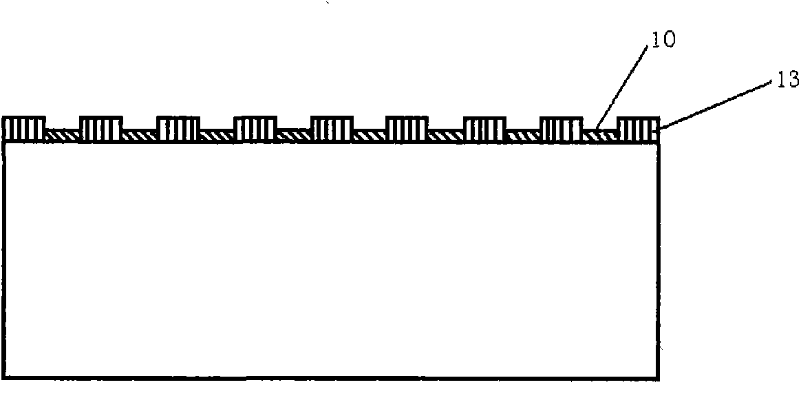
[0016] The sample adopts the solar cell substrate that has completed the PN junction diffusion process and deposited the anti-reflection film 10 . Firstly, the stamper 11 is made, and the corresponding rectangular tooth stamper is designed according to the grid electrode structure on the front of the solar cell. The laser groove method is used to make the rectangular tooth protrusions of the stamper have a width of 80 μm and a height of 100 μm. Coat a layer of diamond carbon film on the mold to avoid adhesion between the stamper and the polymer coating during separation; then spin-coat a plastic film polymer layer 12 with a thickness of 20 μm on the front of the silicon battery; put the battery substrate into the embossing machine And press the stamper on the plastic film and pressurize; remove the stamper to form a corresponding rectangular tooth pattern on the battery substrate; use diluted acetone to etch away the remaining plastic film layer 12 at the groove, and then use h...

Embodiment 2

[0018] The sample adopts the solar cell substrate that has completed the PN junction diffusion process and deposited the anti-reflection film 10 . It is 40 μm that adopting the same method as embodiment one to make protruding width, and height is the rectangular tooth stamper 11 of 50 μm, and on the rectangular tooth stamper, coat a layer of diamond carbon film, avoid adhesion with polymer coating; Spray a plastic film polymer layer 12 with a thickness of 20 μm on the front of the battery; put the battery substrate into the embossing machine and press the stamper on the plastic film to pressurize; remove the stamper to form a corresponding rectangle on the battery substrate Tooth pattern; use diluted acetone to etch away the remaining plastic film layer at the groove, and then use hydrofluoric acid solution to remove the anti-reflection coating to expose the front of the silicon cell; use electroless plating to deposit a nickel seed layer on the groove, and then A layer of 10 ...


PUM


Abstract

The invention relates to a method for manufacturing a front side grid line electrode of a solar battery. The technical scheme of the method is as follows: the method for manufacturing the front side grid line electrode of the solar battery is characterized in sequentially comprising the following steps of: 1. acting a rectangular tooth press mould with proper aspect ratio on the front side of the thin polymer film-coated solar battery to form into a rectangular tooth pattern corresponding to the press mould; 2. removing a polymer film at a groove and reducing a reflection coating by means of chemical corrosion; and 3. performing a selective metal chemical plating technology and an electroplating technology to manufacture the grid line electrode. With the scheme, the method overcomes the disadvantage of the prior art, provides a new scientific and reasonable method for manufacturing the front side grid line electrode of the solar battery, prevents a battery substrate from being damaged, leading the press mould to be hardly deformed, being suitable for recycle in industrialization, and reducing the cost.

Description

technical field [0001] The invention relates to a method for manufacturing a grid line electrode on the front side of a solar cell. technical background [0002] The front grid electrode of the solar cell is used to collect the current emitted by the solar cell. The performance of the electrode directly affects the energy conversion efficiency of the cell. The ideal electrode should have low series resistance and small surface coverage. In the current photovoltaic industry, screen printing and trench buried gate are the main electrode fabrication techniques for crystalline silicon solar cells. [0003] Screen printing technology is to use the principle that the mesh part of the screen graphics is transparent to the paste, and the non-graphic part of the mesh is impermeable to the paste. It is composed of five major elements, namely the screen, the scraper, the paste, the workbench and the substrate. . To obtain a grid wire electrode with excellent electrical properties, it...

Claims


Application Information

Patent Timeline
Patent Type & Authority Applications(China)
IPC IPC(8): H01L31/18
CPCY02P70/50
Inventor 万青郑策方旭昶
Owner 浙江日兆新能源开发有限公司
Learn More