Roller for machining metal foil
A metal foil and metal material technology, applied in metal processing equipment, metal rolling, metal rolling, etc., can solve the problems of a large number of cracks, defects, and inability to form metal foils in ceramic rolls, and achieve non-wear and high durability sexual effect
- Summary
- Abstract
- Description
- Claims
- Application Information
AI Technical Summary
Problems solved by technology
Method used
Image
Examples
Embodiment 1
[0097] A Nb:YAG laser was installed as a laser oscillator in a laser processing apparatus (manufactured by Spectra-Physics Co., Ltd.). The intensity of the laser light output from the processing head was set to 23 μJ per irradiation. In addition, adjust the condenser lens and focal length, and set the imaging magnification of the processing head to 16 times. That is, the imaging size of the processing head is 1 / 16 times the opening of the mask for laser processing. As a mask for laser processing, a mask having a thickness of 0.3 mm and a size of 22 mm×22 mm in size of 22 mm×22 mm in size of 22 mm×22 mm stainless steel plate (SUS304) was subjected to electrical discharge machining to form a substantially rhombic laser passing hole. The diamond-shaped opening diameter (long diagonal length) of the laser passing hole is 0.32 mm. The short diagonal length is 0.16mm.
[0098] Between the roller rotation device and the tailstock of this laser processing device, a forged steel rol...
Embodiment 2
[0102] In addition to using cemented carbide rollers (manufactured by Fuji Daisu Co., Ltd., diameter 50mm, width 100mm, Rockwell hardness: HRA90.0 on A scale, flexural strength: 3.1GPa, containing tungsten carbide particles and cobalt (bonding) Agent)) except that, it carried out similarly to Example 1, and produced the roll for metal foil processing of this invention.
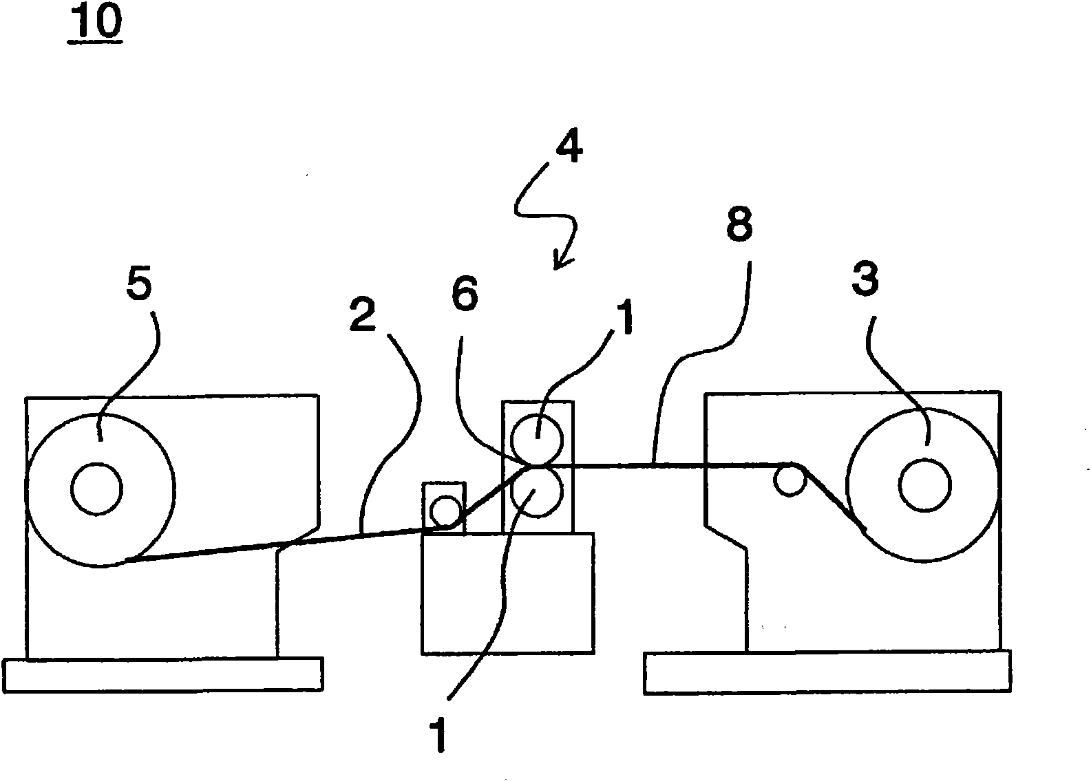
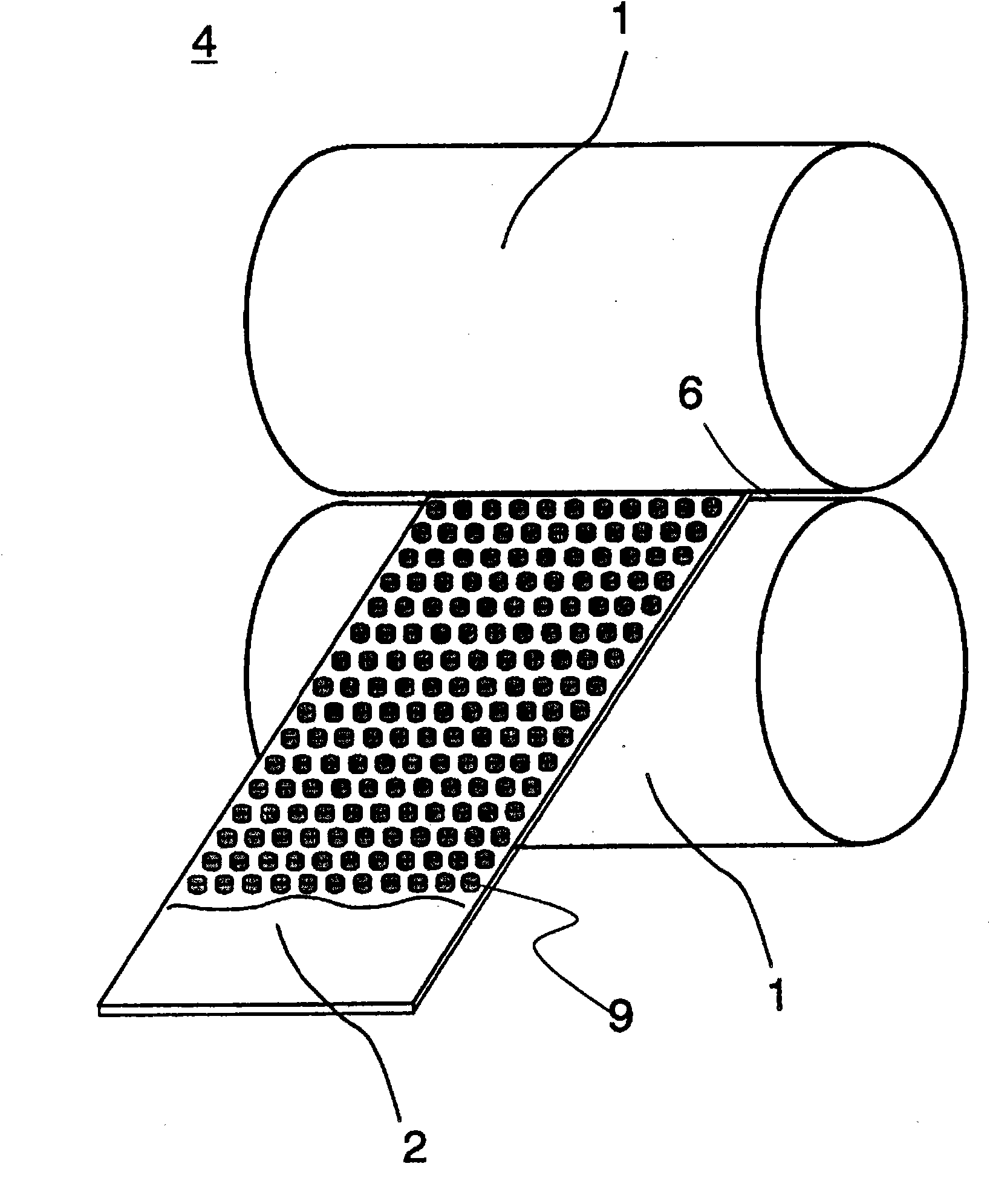
[0103] Two of the metal foil processing rollers are installed on the metal foil processing device 10, except that the pressure on the crimping nip is changed from about 14.7kN·cm (1500kgf / cm) to about 9.8kN·cm (1000kgf / cm) Except that, it processed similarly to Example 1, width 80mm, and the tough copper foil of thickness 26 micrometers. Protrusions corresponding to the recesses of the metal foil processing roller were formed on the surface of the processed copper foil. The average height of 10 convex portions measured with a laser microscope (VK-9500) was 6.5 μm. 100 m / roll, a total of 10 rolls of 1000 m co...
Embodiment 3
[0105] In addition to using a hard roll (manufactured by Fuji Daisu Co., Ltd., diameter 50mm, width 100mm, Rockwell hardness: HRA89.0 on the A scale, flexural strength: 3.3GPa, containing tungsten carbide particles and cobalt (binder) ) except that the roll for metal foil processing of the present invention was produced in the same manner as in Example 1.
[0106] Two of the metal foil processing rollers are installed on the metal foil processing device 10, except that the pressure on the crimping nip is changed from about 14.7kN·cm (1500kgf / cm) to about 9.8kN·cm (1000kgf / cm) Except that, it processed similarly to Example 1, width 80mm, and the tough copper foil of thickness 26 micrometers. Protrusions corresponding to the recesses of the metal foil processing roller were formed on the surface of the processed copper foil. The average height of 10 convex portions measured with a laser microscope (VK-9500) was 6.3 μm. Furthermore, processing was performed on 100 m / roll, 20 ro...
PUM
| Property | Measurement | Unit |
|---|---|---|
| flexural strength | aaaaa | aaaaa |
| diameter | aaaaa | aaaaa |
| flexural strength | aaaaa | aaaaa |
Abstract
Description
Claims
Application Information
 - R&D
- Intellectual Property
- Life Sciences
- Materials
- Tech Scout
- Unparalleled Data Quality
- Higher Quality Content
- 60% Fewer Hallucinations
Browse by: Latest US Patents, China's latest patents, Technical Efficacy Thesaurus, Application Domain, Technology Topic, Popular Technical Reports.
© 2025 PatSnap. All rights reserved.Legal|Privacy policy|Modern Slavery Act Transparency Statement|Sitemap|About US| Contact US: help@patsnap.com


