Miniaturized handheld deep and small hole compound deburring device

A technology for removing burrs and deep holes, applied in the field of mechanical processing tools, can solve the problems of difficult removal, high cost, unfavorable flexibility of assembly line operations, etc., and achieve the effect of eliminating processing marks and improving surface quality

Inactive Publication Date: 2011-12-28
CHINA PRECISION ENG INST FOR AIRCRAFT IND AVIC
View PDF0 Cites 0 Cited by
  • Summary
  • Abstract
  • Description
  • Claims
  • Application Information

AI Technical Summary

Problems solved by technology

Because the parts where these burrs are generated go deep into the interior of the parts, the generated burrs cannot be seen or touched, and it is difficult to remove them. If they are not removed cleanly, it will cause blockage of the oil circuit, affect the reliability and life of the parts, and even make the hydraulic system function failure, which will bring great hidden danger to the hydraulic oil circuit
[0003] For this kind of complex structure, there are many deep and small holes communicating with each other inside the burrs. At present, the technology of manual burrs is basically used, that is: with the help of cold light source and endoscope observation, with self-made hand tools (special-shaped Scraper, file, special grinding tool, etc.) to remove burrs, labor intensity is high, cycle time is long, cost is high, efficiency is low, it is difficult to ensure consistent product quality, it is not conducive to assembly line operation during batch production and to realize the flexibility of product manufacturing. It is also easy to produce undue scratches during the deburring process, resulting in rework or even scrapping, which increases the manufacturing cost of the part by more than 10%

Method used


Image

  • Miniaturized handheld deep and small hole compound deburring device
  • Miniaturized handheld deep and small hole compound deburring device
  • Miniaturized handheld deep and small hole compound deburring device

Examples


Embodiment

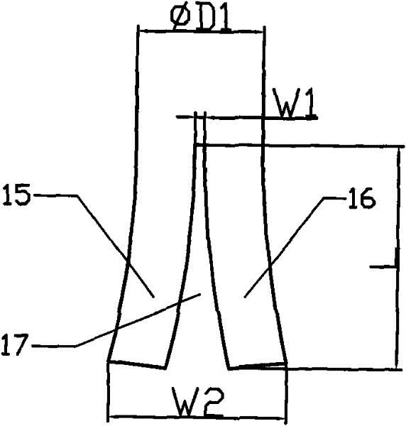
[0012] Design of the deburring tool:

[0013] The deburring tool is a cylindrical elongated metal rod made of tool steel. Its diameter ФD1 is Ф0.2mm smaller than the diameter of the small hole to be deburred. There is a transparent opening rectangular groove 17 in the center of the front end of the deburring tool, and the transparent opening rectangular groove is centered relative to the outer circle of the metal rod. The width W1 of the transparent open rectangular groove is 0.25 mm to 0.3 mm, and the depth L of the rectangular groove is 3 to 5 times the diameter of the metal rod ΦD1. Due to the existence of the transparent opening rectangular groove 17, the two branch parts 15, 16 formed at the front end of the metal rod will naturally have a certain arc of bending deformation, and because the transparent opening rectangular groove is divided relative to the outer circle of the metal rod, the two The bending deformation of the two branch parts is exactly the same and has e...


PUM


Abstract

The invention belongs to mechanical processing tools, and relates to a hand-held deep and small hole composite deburring device for miniaturization of complex shell parts. The deburring device includes a worktable, a fixed support frame, a vibration generator, and a vibration converter equipped with a deburring tool. The fixed support frame and the vibration generator are placed on the workbench, and the vibration converter equipped with a deburring tool passes through the steel belt. Installed on a fixed support bracket, the vibration converter of the deburring tool is connected with the vibration generator, the grinding powder container is installed on the workbench, the water container is higher than the grinding powder container and placed on the workbench; the deburring tool is connected with the vibration converter , The deburring tool is a cylindrical slender metal rod, and the center of the front end of the metal rod has a transparent opening rectangular groove with a width of 0.25 mm to 0.3 mm, and the depth of the rectangular groove is 3 to 5 times the diameter of the metal rod. The invention is suitable for deburring deep and small holes with a length-to-diameter ratio greater than 40 and a diameter less than Ф3 mm, and the processing efficiency is increased by more than 50% to 70%.

Description

technical field [0001] The invention belongs to mechanical processing tools, and relates to a hand-held deep and small hole composite deburring device for miniaturization of complex shell parts. Background technique [0002] The hydraulic valve body and shell are the basic assembly parts of the hydraulic system. Compared with other parts, its structure is complex, and there are many criss-cross holes inside. They communicate with each other to form a complete oil circuit system. Among these intersecting holes, the diameter of a considerable part of the holes is less than Ф3mm, and the aspect ratio is greater than 40. During the processing of these holes, burrs are inevitably generated at the intersections. Because the parts where these burrs are generated go deep into the interior of the parts, the generated burrs cannot be seen or touched, and it is difficult to remove them. If they are not removed cleanly, it will cause blockage of the oil circuit, affect the reliability ...

Claims


Application Information

Patent Timeline
Patent Type & Authority Patents(China)
IPC IPC(8): B24B23/04B24B9/00B24B5/48
Inventor 王婕迟宪唐辉民
Owner CHINA PRECISION ENG INST FOR AIRCRAFT IND AVIC
Why Eureka
Try Eureka