Phase Laser Rangefinder and Laser Rangefinder Method

A phase laser ranging and laser technology, which is applied in the direction of measuring distance, instruments, measuring devices, etc., can solve the problems of long distance measurement, achieve the effects of long distance measurement, reduce labor intensity, and simple structure

Inactive Publication Date: 2011-12-28
WUHAN UNIV
View PDF4 Cites 0 Cited by
  • Summary
  • Abstract
  • Description
  • Claims
  • Application Information

AI Technical Summary

Problems solved by technology

[0003] High precision, long range, and fast speed are the core and difficulties of laser range finders, but the current traditional measurement methods and domestic laser range finders are difficult to meet the above requirements at the same time

Method used


Image

  • Phase Laser Rangefinder and Laser Rangefinder Method
  • Phase Laser Rangefinder and Laser Rangefinder Method
  • Phase Laser Rangefinder and Laser Rangefinder Method

Examples


Embodiment Construction

[0027] The design of the present invention in terms of optical path, circuit and algorithm will be described in detail below in conjunction with the drawings and embodiments.

[0028] (1) Optical path part

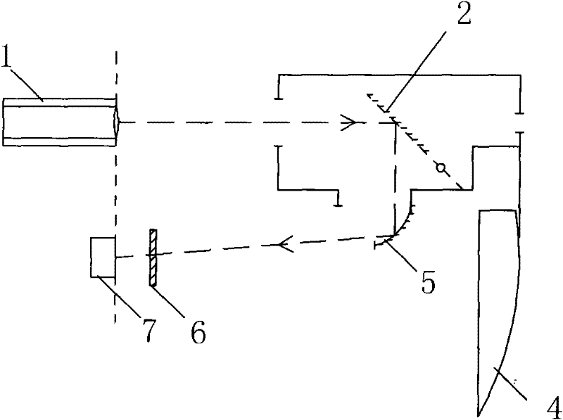
[0029] The optical path part can adopt a structure with double mirrors or without double mirrors. The difference between the two is that the former structure is equipped with double mirrors to increase the measuring range.

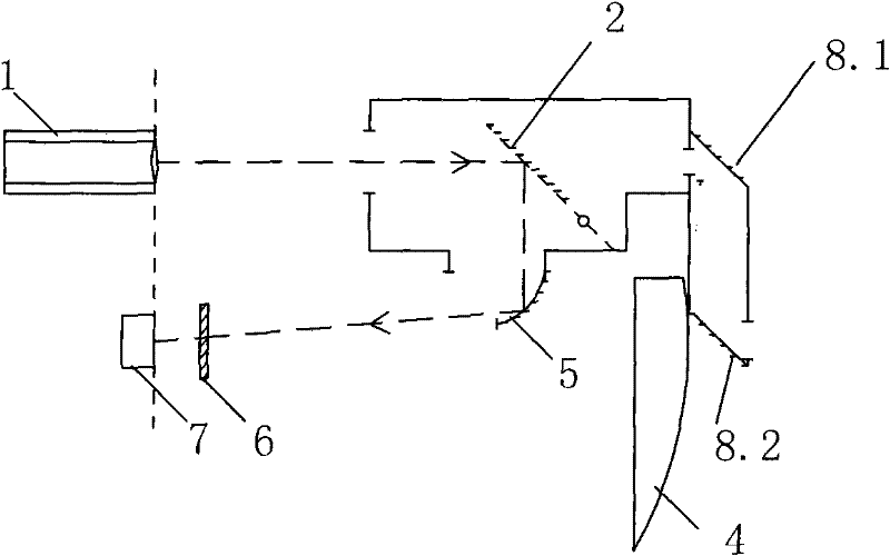
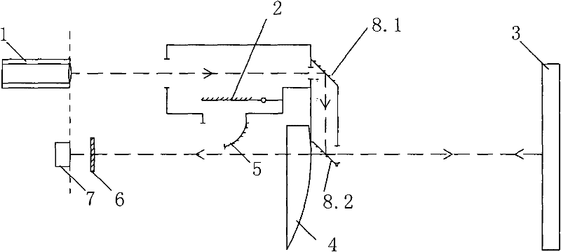
[0030] Referring to Fig. 1, the double reflector structure includes a laser emitter 1, a baffle reflector 2, a double reflector (the reflector 8.1 and the reflector 8.2 arranged opposite to each other on the mirror surface are formed), an objective lens 4, a concave reflector 5, an optical filter 6 and the detector 7, wherein the baffle reflector 2 is placed in front of the laser transmitter 1, and the double mirrors, objective lens 4, concave reflector 5 and optical filter 6 are placed in front of the detector 7 in sequence. Such as Figure 1a , The...


PUM


Abstract

The optical path part of the phase laser rangefinder provided by the present invention can adopt a structure containing double reflectors or a structure without double reflectors, and adopts single-chip microcomputer technology to automatically give measurement results, including search processing for the number of integer wavelengths and for non-integer wavelengths Phase difference detection processing. The invention has simple structure and high integration, and can be made into a hand-held phase laser rangefinder product that is easy to carry and use, which can reduce people's labor intensity and improve work efficiency. The advantages of long distance and fast measurement speed.

Description

technical field [0001] The invention relates to the technical field of laser measurement, in particular to a phase laser rangefinder and a corresponding laser rangefinder method. Background technique [0002] Distance measurement is often used in building construction, interior decoration, traffic accident handling, and dangerous location measurement (such as nuclear radiation, high voltage, etc.). The current measurement method is to use a meter ruler and tape measure. This measurement method has low precision, time-consuming and laborious, and slow speed. However, the traditional laser distance measuring instrument is large in size, low in accuracy, and slow in measurement speed. Many existing The problem caused great inconvenience to the surveyors. [0003] High precision, long range, and fast speed are the core and difficulties of laser range finders, but the current traditional measurement methods and domestic laser range finders are difficult to meet the above require...

Claims


Application Information

Patent Timeline
Patent Type & Authority Patents(China)
IPC IPC(8): G01C3/00G01S17/08
Inventor 许贤泽于涛
Owner WUHAN UNIV
Why Eureka
Try Eureka