
Sand core structure for precasting high-pressure oil channel of engine cylinder cover and precasting method

An engine cylinder head, high-pressure oil technology, applied in the directions of casting molds, cores, casting mold components, etc., can solve the problems of increasing the burden of blank foundries and OEMs, reducing labor efficiency, and increasing processing hours, etc. The effect of promoting, improving labor productivity, and improving production efficiency

Active Publication Date: 2010-09-01
CHERY AUTOMOBILE CO LTD
View PDF4 Cites 16 Cited by
  • Summary
  • Abstract
  • Description
  • Claims
  • Application Information

AI Technical Summary

Problems solved by technology

This not only reduces labor efficiency due to increased processing man-hours, but also increases the production cost before testing in the event of waste products caused by leakage, which increases the burden on both the rough foundry and the OEM
Due to the special structural characteristics of the high-pressure oil passage, the molten metal is prone to turbulent flow and gas entrainment during the filling process, and isolated liquid phase areas are easily formed at the hot joints of the oil passage during the solidification process, resulting in loosening and shrinkage cavities. These unfavorable factors are likely lead to casting scrap

Method used


Image

  • Sand core structure for precasting high-pressure oil channel of engine cylinder cover and precasting method
  • Sand core structure for precasting high-pressure oil channel of engine cylinder cover and precasting method
  • Sand core structure for precasting high-pressure oil channel of engine cylinder cover and precasting method

Examples


Embodiment Construction

[0032] The present invention will be further described below in conjunction with the accompanying drawings and specific embodiments, but not as a limitation of the present invention.

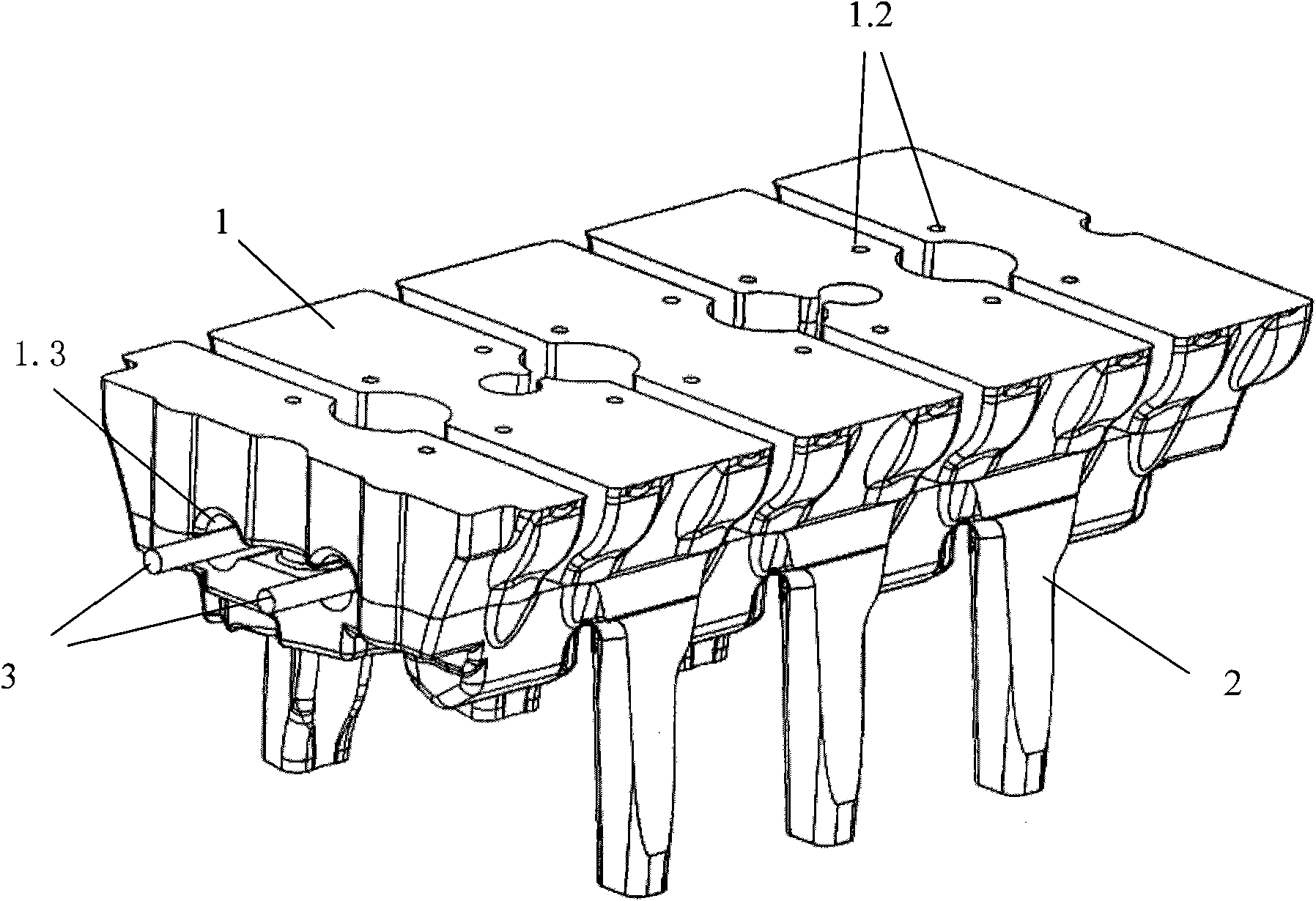
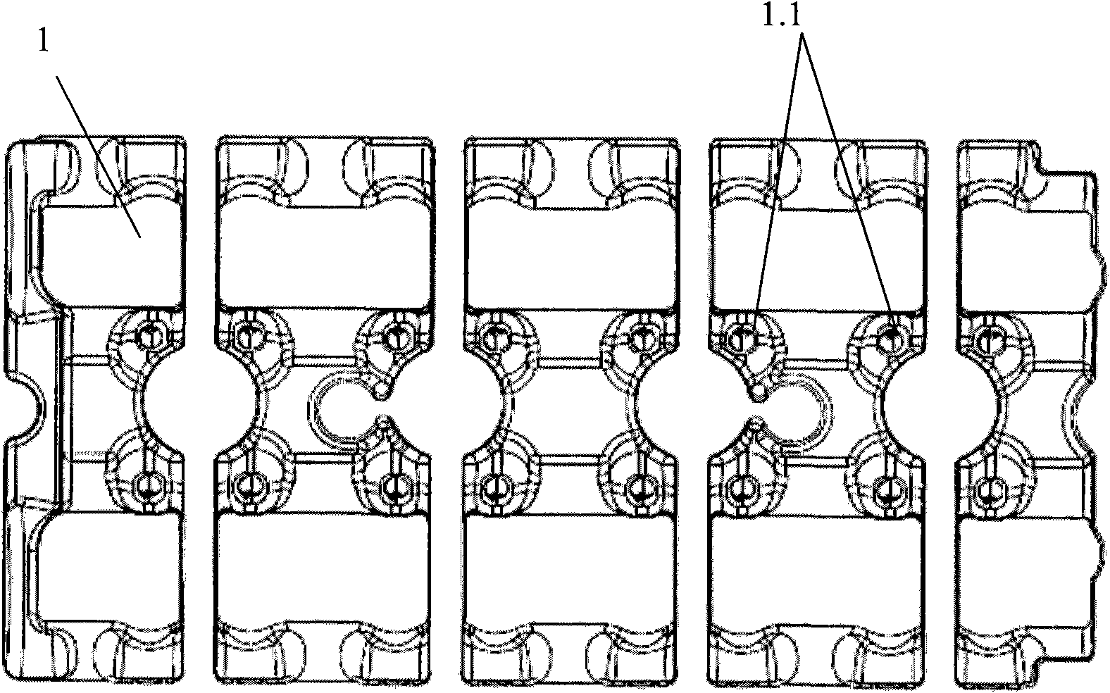
[0033] see figure 1 , the sand core structure used for precasting the high-pressure oil passage of the engine cylinder head, the middle of the lower part of the riser core 1 is correspondingly provided with a through hole 1.3, and the high-pressure oil passage sand core 3 is arranged in the through hole 1.3.

[0034] With the structure of the embodiment of the present invention, after the aluminum alloy cylinder head high-pressure oil passage is pre-cast, the leak test of the oil passage hole can be carried out in the foundry, which can not only strengthen the foundry's ability to control the oil passage leakage rejection rate, but also It can shorten the cycle of rectification of quality problems, thereby reducing the scrap rate in the process of processing. The risk of quality problem claims ...


PUM


Abstract

The invention discloses a sand core structure for precasting a high-pressure oil channel of an engine cylinder cover. In the sand core structure, a through hole is formed on a dead head core; a high-pressure oil channel sand core is arranged in the through hole; the high-pressure oil channel sand core comprises a high-pressure oil channel hole sand core and a push rod hole sand core; the push rod hole sand core is arranged on the high-pressure oil channel hole sand core; a positioning hole is formed on an internal arm of the through hole; the push rod hole sand core is fixed in the positioning hole; the push rod hole sand core is provided with a core head; and a vent hole is formed on the dead head core corresponding to the positioning hole. The precasting method comprises the following steps of: firstly, matching and adhering the high-pressure oil channel sand core with the dead head core; secondly, matching and adhering the dead head core with an oil pool core; thirdly, making a cylinder cover water jacket sand core and an air duct sand core in an external die according to a normal sequence; and finally, placing the assembled sand cores into a metal external die for pouring to obtain the high-pressure oil channel precast cylinder cover after the sand cores are solidified. The sand core structure and the precasting method have the advantages of improving labor productivity, reducing processing cost, reducing rejection rate and improving the quality control effect of cast blanks.

Description

technical field [0001] The invention relates to a high-pressure oil passage of an engine cylinder head, in particular to a sand core structure and a pre-casting method for precasting a high-pressure oil passage of an engine cylinder head. Background technique [0002] Domestic engine aluminum alloy cylinder heads mostly use the gravity casting process, and a small amount of them use the low pressure casting process. The structural feature of the high-pressure oil passage in the aluminum alloy cylinder head of the engine is generally a hole with a length of more than 400mm and a diameter of less than 10mm. At present, the high-pressure oil passage holes of the cylinder head are first cast into "solid", and then obtained by machining. Since the structure is a slender hole, only the method of deep hole drilling at both ends can be considered in the processing technology. The position of the high-pressure oil channel in the aluminum alloy cylinder head in the prior art is usua...

Claims


Application Information

Patent Timeline
IPC IPC(8): B22C9/10
Inventor 田身军张炳荣项大伟徐帅
Owner CHERY AUTOMOBILE CO LTD
Learn More