High dynamic range radio frequency signal power detection circuit

A power detection circuit, radio frequency signal technology, applied in the direction of measuring electric power, measuring electric variables, electric vehicles, etc., can solve the problems of limited working range of effective accuracy, limited range of exponential approximation, difficult radio frequency signal power detection, etc., to achieve extended power Detection range, low power consumption, effect of saving low power consumption

Inactive Publication Date: 2010-09-01
FUDAN UNIV
View PDF5 Cites 10 Cited by
  • Summary
  • Abstract
  • Description
  • Claims
  • Application Information

AI Technical Summary

Problems solved by technology

It is easy to know that such a detection using the rectification characteristics of the tube often has a limited working range of effective accuracy, especially when the logarithm-linear relationship is to be realized, the sub-threshold working range is small, and the exponential approximation range is also very limited, making it difficult to achieve high dynamics Range high precision RF signal power detection

Method used


Image

  • High dynamic range radio frequency signal power detection circuit
  • High dynamic range radio frequency signal power detection circuit
  • High dynamic range radio frequency signal power detection circuit

Examples


Embodiment Construction

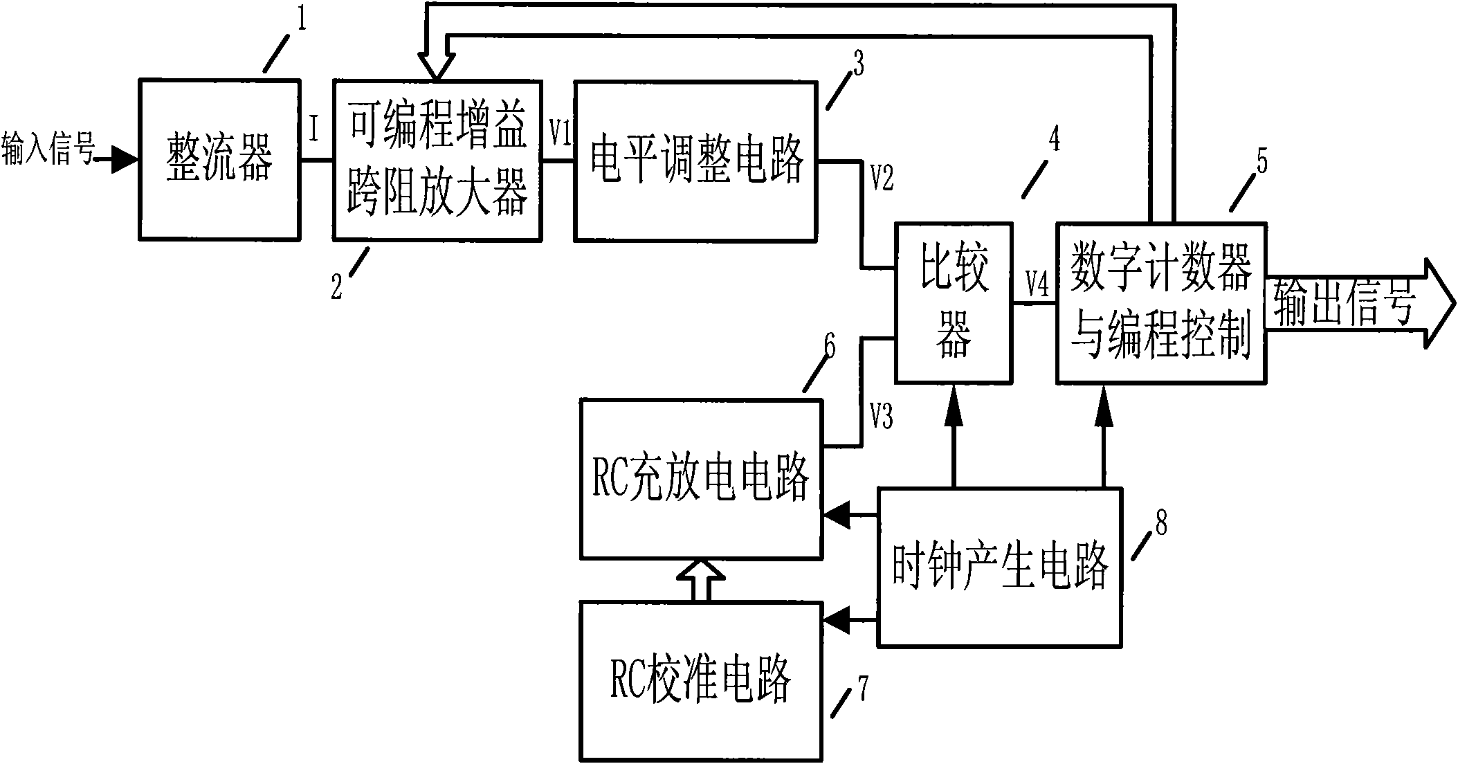
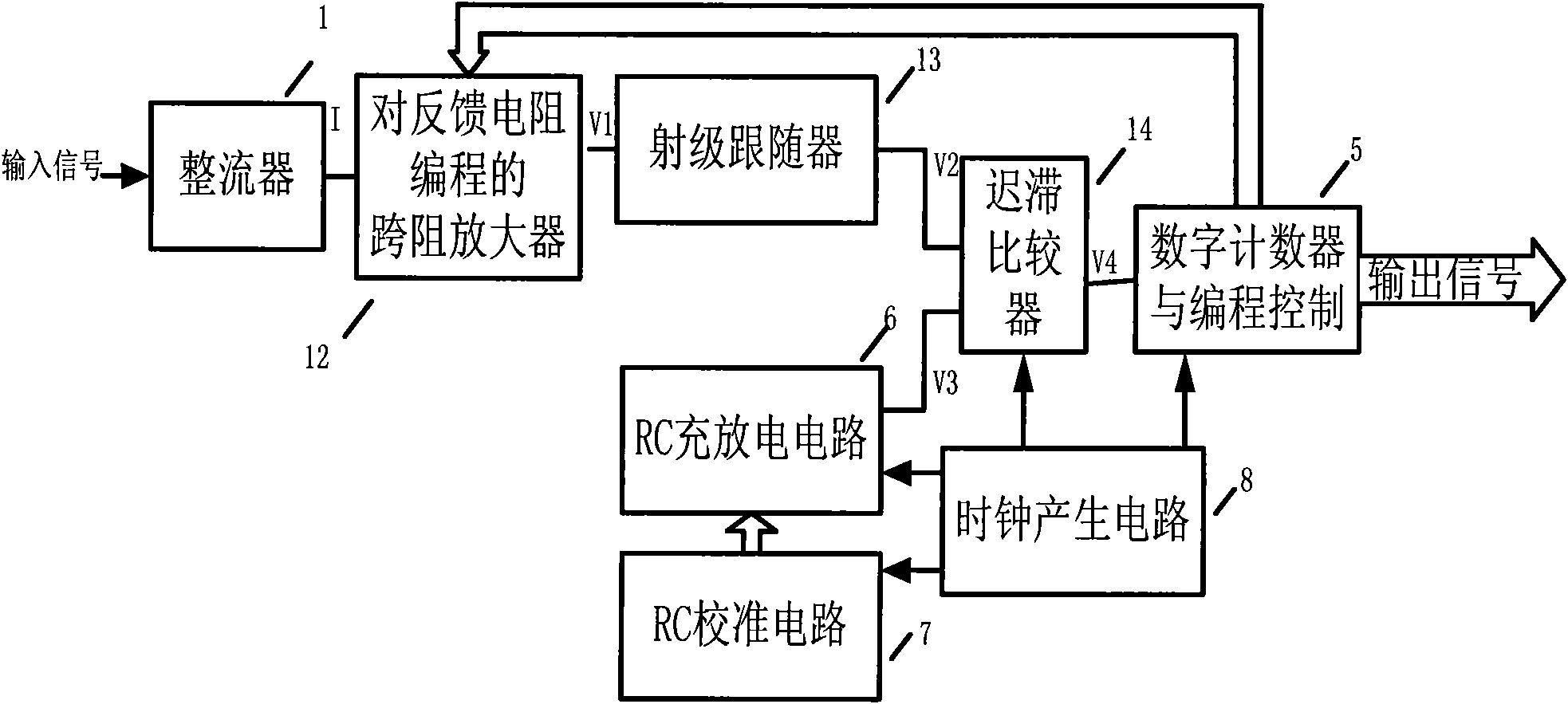
[0023] Combine below image 3 , a specific example of implementing the present invention is described in detail.

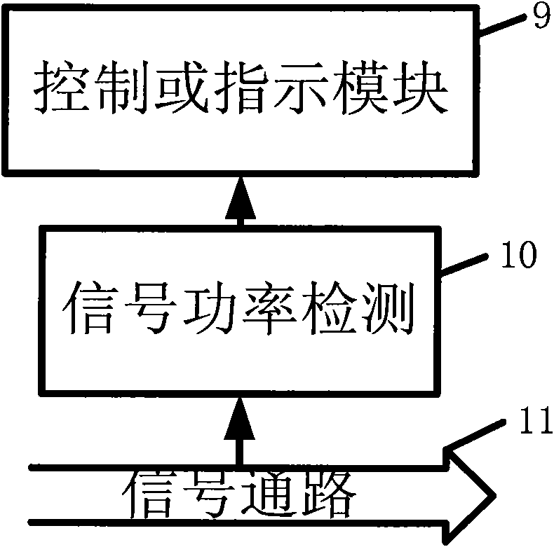
[0024] exist image 3 In , a resistor-feedback op amp realizes the current-to-voltage conversion by programming the feedback resistor (12). A transimpedance amplifier (6) with programmable gain is formed, and the gain is controlled by a number of digital codes provided by the counter and the feedback control module (5). The emitter follower (13) acts as a simple level adjustment (7). figure 1 The comparator (4) in adopts the hysteresis comparator (17) to realize here. The hysteresis comparator acts as a voltage comparator (4), and the hysteresis function is introduced to resist noise and signal fluctuations.

[0025] When a certain power signal is input, the rectifier outputs a current proportional to the average power of the signal, and the current flows through the transimpedance amplifier fed back by the resistor to obtain a voltage signal proportional to t...


PUM


Abstract

The invention belongs to the technical field of integrated circuit design, in particular a radio frequency signal power detection circuit. The radio frequency signal power detection circuit comprises a rectifier, a gain-variable transimpedance amplifier, a level adjusting circuit, a high-precision comparator, a counter and automatic gain control circuit, an RC calibrating circuit and a clock generation and control circuit. The power detection circuit realizes the function of detecting the frequency signal power through voltage detection and programming adjustment and control of the dynamic range of the detection circuit according to the input signal power. In order to realize the high precision and high dynamic range, the RC charging and discharging circuit is provided with the special RC calibrating circuit. The clock generation circuit is used for controlling the comparator, the RC charging and discharging circuit, the RC calibrating circuit and the counter and automatic gain control circuit to work. With the RC charging and discharging circuit, the RC calibrating circuit and the automatic gain control circuit additionally arranged in the power detection circuit, the invention realizes the high dynamic range and high-precision logarithmic-to-linear power detection for the radio frequency signal.

Description

technical field [0001] The invention belongs to the technical field of integrated circuit design. In particular, it relates to a transceiver in a wireless communication system, a radio frequency signal power detection circuit with built-in self-detection and error correction for analog and radio frequency circuits. Background technique [0002] The radio frequency signal power detection circuit is one of the power detection circuits. It has a wide range of applications in wireless communication systems, design for testability of analog radio frequency circuits, and self-testing and error-correction. figure 1 The functions of the power detection circuit 10 in analog and radio frequency circuits are described. It is a bridge connecting the control module or indicating module 9 and the signal 11 in the signal path, it can detect the instant signal power of the required point in the signal path, and the electrical quantity representing the signal power obtained through its det...

Claims


Application Information

Patent Timeline
IPC IPC(8): G01R21/00
Inventor 黄烈超王肖谈熙闫娜闵昊
Owner FUDAN UNIV
Why Eureka
Try Eureka