Light transmission module, electronic device, and manufacturing method of light transmission module

A technology for electronic equipment and optical transmission, which is applied to the coupling of optical waveguides, light guides, optics, etc., and can solve the problems of large-design light-emitting and receiving elements 13, increased occupied area of ​​optical transmission modules, and increased costs.

Inactive Publication Date: 2010-09-01
ORMON CORP
View PDF3 Cites 5 Cited by
  • Summary
  • Abstract
  • Description
  • Claims
  • Application Information

AI Technical Summary

Problems solved by technology

However, the size of the light-emitting and receiving element 13 needs to be designed larger, resulting in an increase in cost
In addition, the occupied area of ​​the optical transmission module as a whole increases

Method used


Image

  • Light transmission module, electronic device, and manufacturing method of light transmission module
  • Light transmission module, electronic device, and manufacturing method of light transmission module
  • Light transmission module, electronic device, and manufacturing method of light transmission module

Examples


Deformed example 1

[0130] In the configuration of the optical transmission module 1 of the embodiment of the present invention, for figure 1 A modified example of the configuration shown will be described. Figure 5 is a cross-sectional view showing a schematic result of the optical transmission module according to Modification 1. FIG. In addition, in Figure 5 In , in order to simplify the structure of Modification 1, the thin film optical waveguide 2 is omitted.

[0131] Such as Figure 5 As shown, the optical transmission module 1 of Modification 1 has dummy pads 9 a and 9 b. The dummy pads 9 a and 9 b are provided on the surface of the substrate 6 opposite to the surface on which the light emitting and receiving elements 3 are mounted. The dummy pads 9 a are arranged so as to overlap the connection portions where the substrate wiring 5 and the bonding wiring 7 are connected when projected onto a plan view. In addition, the dummy pads 9b are arranged to overlap with the light emitting a...

Deformed example 2

[0138] In the configuration of the optical transmission module 1 according to the embodiment of the present invention, the figure 1 A modified example of the configuration shown will be described. Image 6 is a cross-sectional view showing a schematic configuration of an optical transmission module according to Modification 2.

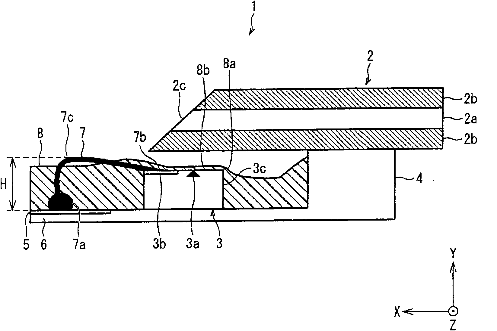
[0139] Such as Image 6 As shown, in the optical transmission module 1 of Modification 2, the front end 2d of the thin-film optical waveguide 2 in the light transmission direction (X direction) is arranged at the contact point (end 7b) of the bonding wire 7 with the electrode pad 3b and the light emitting and receiving terminal. Between points 3a. The thin-film optical waveguide 2 is held by the height compensating member 4 and has an optical path conversion mirror portion 2 c whose at least one end portion is obliquely processed. Furthermore, the front end portion 2d may also be referred to as the light transmission direction front end of the opti...

Deformed example 3

[0144] In the structure of the optical transmission module 1 of the embodiment of the present invention, for figure 1 Modifications of the shown configurations will be described. As described above, the optical transmission path to which the present invention is applicable is not limited to a thin-film optical waveguide, and may be any member as long as it has a function of transmitting light. The optical transmission module 1 of Modification 3 has an optical fiber or a lens as an optical transmission path. first, Figure 7 It is a cross-sectional view showing a schematic configuration of an optical transmission module 1 having an optical fiber as an optical transmission path.

[0145] Such as Figure 7 As shown, the optical fiber 21 is formed of a core 21a having a high refractive index and a cladding 21b having a small refractive index provided in contact with the periphery of the core 21a. The optical fiber 21 repeats total reflection and transmission of an optical sig...


PUM


Abstract

A light transmission module, an electronic device, and a manufacturing method of the light transmission module reduces the distance between a light guide and a light emitting and receiving element and inhibits the light coupling loss between the light guide and the light emitting and receiving element. The light transmission module has a light transmission path for transmitting light, an optical element including a light emitting and receiving surface for emitting or receiving an optical signal transmitted by the light transmission path, and having a light emitting and receiving point with a function of photoelectric conversion and an electrode pad formed on the light emitting and receiving surface, a substrate mounted with the optical element and an electrical wiring, a bonding wiring for electrically connecting the electrode pad and the electrical wiring, and a sealing portion for sealing the optical element. The electrical wiring and the electrode pad are reverse wire-bonded by the bonding wiring. The sealing portion includes an inclined part where a liquid sealing resin material is raised and solidified along a side wall of the optical element by surface tension, and a flat part where the liquid sealing resin material is spread in parallel and solidified along the light emitting and receiving surface, the inclined part and the flat part being coupled.

Description

technical field [0001] The invention relates to an optical transmission module, electronic equipment and a manufacturing method of the optical transmission module. Background technique [0002] In recent years, optical communication networks capable of high-speed and large-capacity data communication have been expanding. It is expected that this optical communication network will be installed in civilian equipment in the future. In addition, for high-speed and large-capacity data transmission, noise countermeasures, and data transmission between substrates in equipment, optical data transmission cables (optical cables) that can use input and output power without changing existing cables are required. As this optical cable, it is preferable to use a thin-film optical waveguide in consideration of flexibility. [0003] The so-called optical waveguide is formed by a core with a high refractive index and a cladding layer with a small refractive index provided in contact with t...

Claims


Application Information

Patent Timeline
Patent Type & Authority Applications(China)
IPC IPC(8): G02B6/42G02B6/122
CPCH01L2224/48091H01L2224/48471G02B6/4214H01L2924/1815G02B6/4212H01L2224/48465H01L2924/01019H01L2924/00014H01L2924/00H01L2224/4554
Inventor 田中纯一鲛岛裕安田成留细川速美
Owner ORMON CORP
Why Eureka
Try Eureka