Coaxial switching remote monitor based on FPGA
A monitor and coaxial technology, applied in the program control of sequence/logic controller, electrical program control, etc., can solve the problems of unreliable system, unguaranteed crash status, limited working speed and efficiency, etc.
- Summary
- Abstract
- Description
- Claims
- Application Information
AI Technical Summary
Problems solved by technology
Method used
Image


Examples
Embodiment Construction
[0009] The present invention will be further described below in conjunction with the accompanying drawings and typical embodiments.
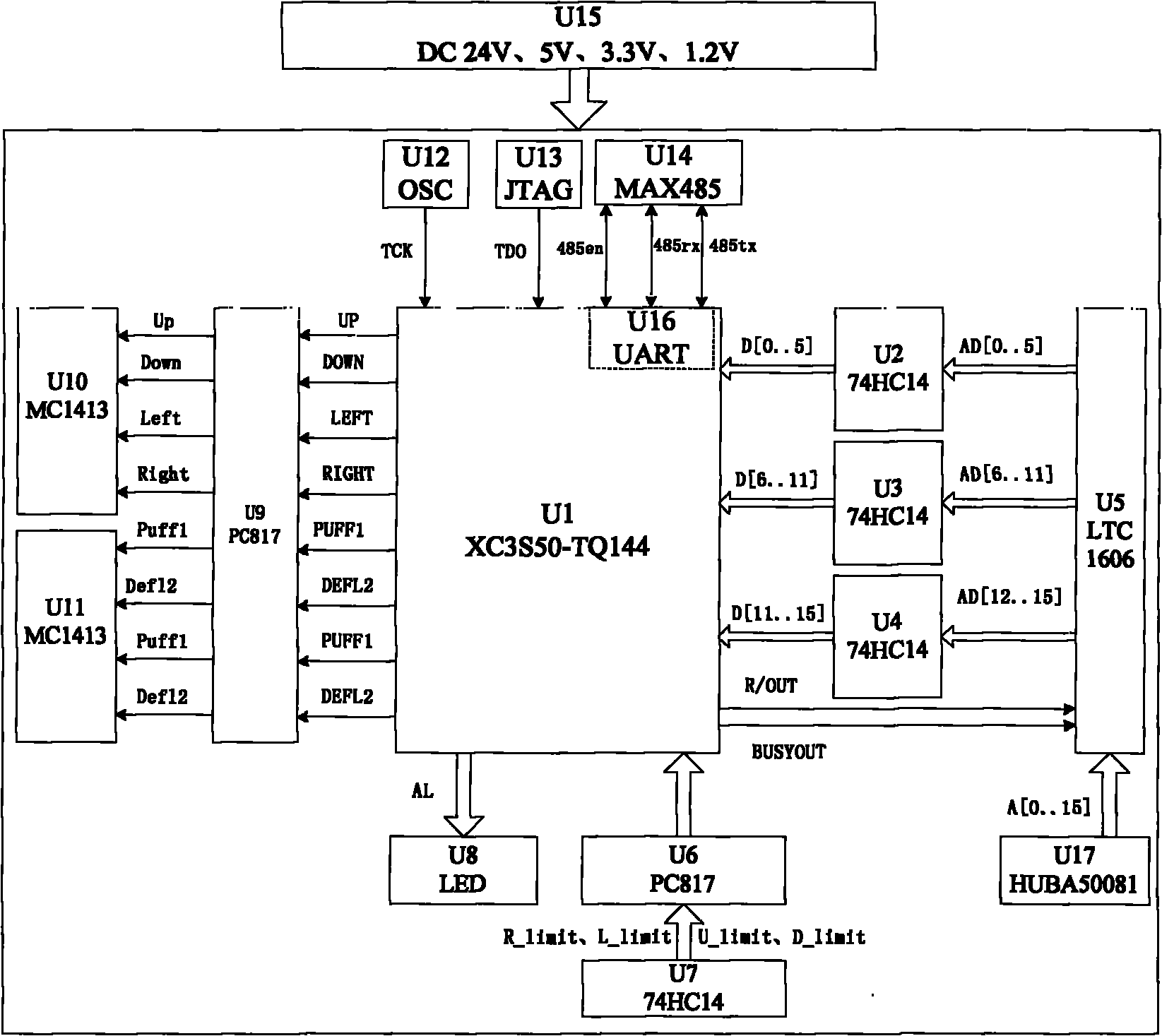
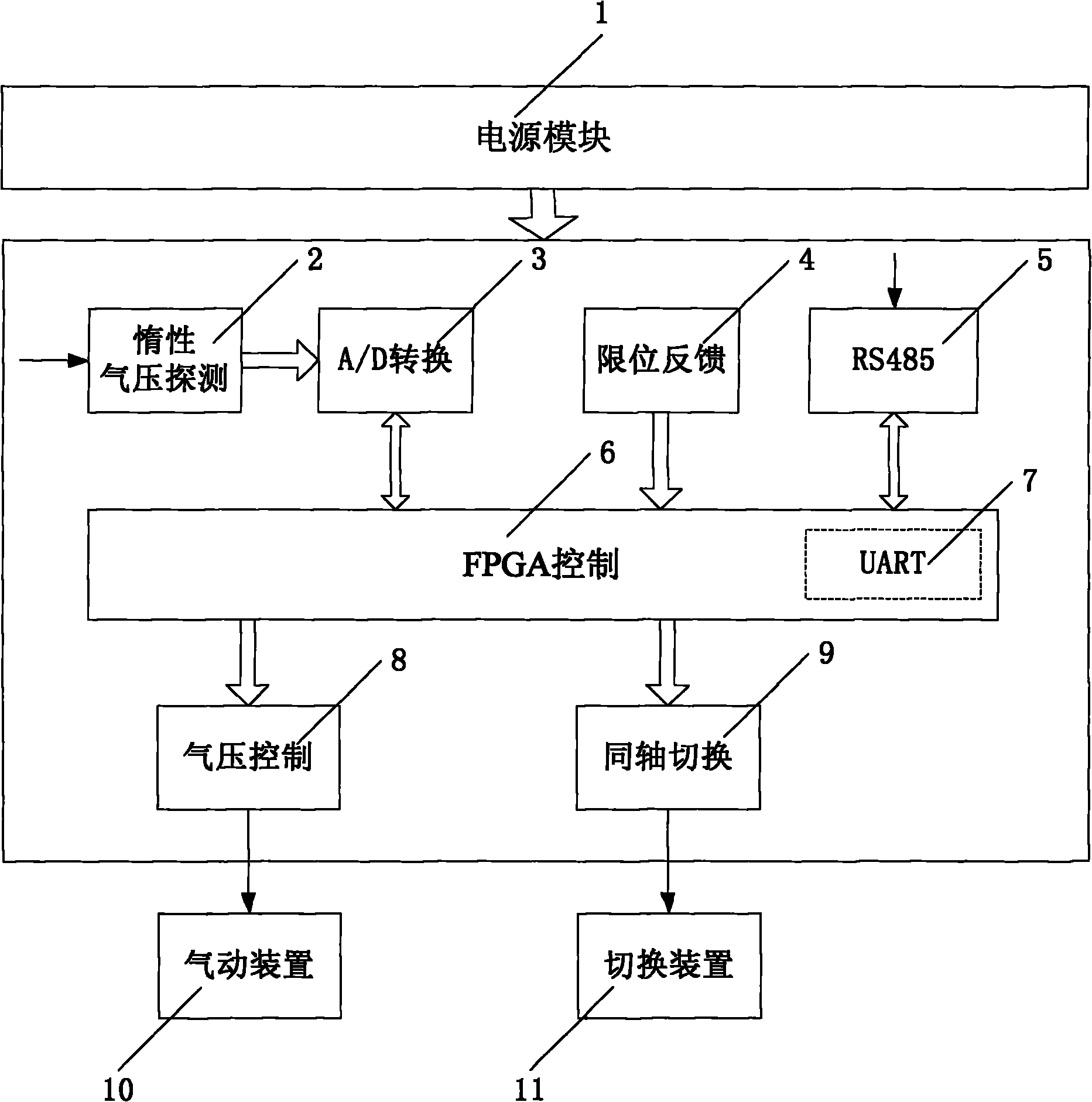
[0010] Refer to attached figure 1 . This embodiment includes 1, a power supply module, which provides the working voltage of each functional chip in the monitoring system; 2, an inert gas detection module, which detects the pressure value of the inert gas in the coaxial transmission line in real time; and 3, an A / D conversion module, which converts the pressure value into Corresponding acquisition voltage; 4 is the limit feedback module, and the stroke sensor signal is sent to the FPGA control module through the feedback module; 5 is the RS485 module, which is responsible for the control command transmission with the remote console; 6 is the FPGA control module; 7 is the UART module , realizing the serial-to-parallel conversion of the transmission data inside the FPGA, realizing the function of the universal asynchronous transceiver; 8 is the a...
PUM
 Abstract
Description
Claims
Application Information
 - Generate Ideas
- Intellectual Property
- Life Sciences
- Materials
- Tech Scout
- Unparalleled Data Quality
- Higher Quality Content
- 60% Fewer Hallucinations
Browse by: Latest US Patents, China's latest patents, Technical Efficacy Thesaurus, Application Domain, Technology Topic, Popular Technical Reports.
© 2025 PatSnap. All rights reserved.Legal|Privacy policy|Modern Slavery Act Transparency Statement|Sitemap|About US| Contact US: help@patsnap.com