Semi-active label

A semi-active, labeling technology, applied to record carriers, instruments, computer parts, etc. used in machines, it can solve the problems of large volume of active labels, loss of function of labels, limited battery life, etc., and achieve a simple and clear circuit structure. The effect of increased life and simple structure

Active Publication Date: 2010-09-15
NANTONG HUALONG MICROELECTRONICS
View PDF3 Cites 15 Cited by
  • Summary
  • Abstract
  • Description
  • Claims
  • Application Information

AI Technical Summary

Problems solved by technology

[0005] 1. Active tags: There is a battery inside, generally has a long reading distance, the longest reading distance is even tens of meters or even hundreds of meters, the disadvantage is that it has a battery and the life of the battery is limited, and its cost is relatively Higher,

Method used


Image

  • Semi-active label
  • Semi-active label
  • Semi-active label

Examples


Example Embodiment

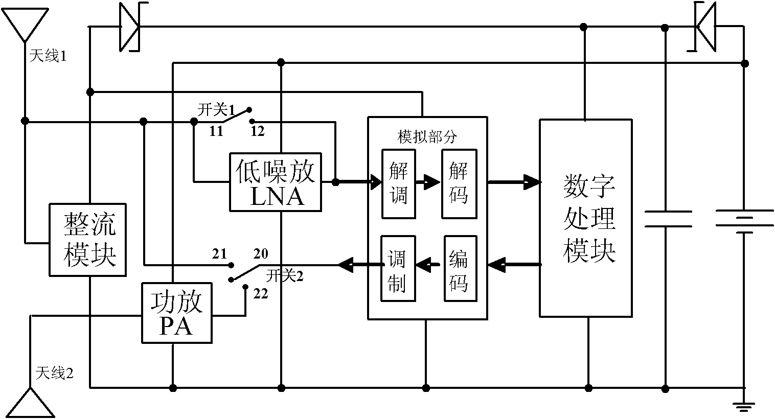
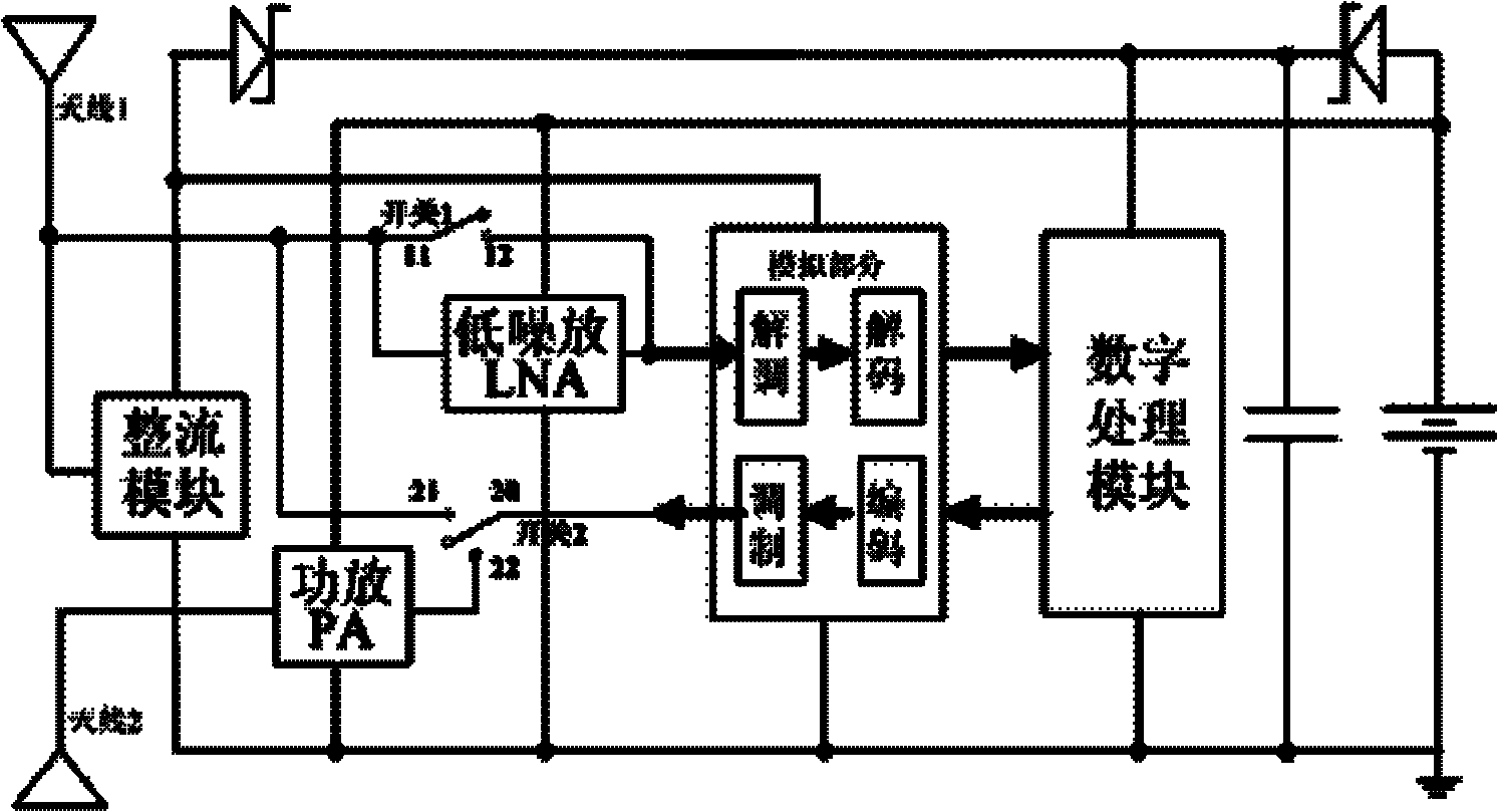
[0021] The semi-active tag structure of the present invention adopts the mode that the analog part of the tag is powered by the rectifier module, and the digital processing module is powered by the battery. The module is powered, and the digital processing module only enters the working state when the reader reads the tag, that is, when the tag receives the relevant command from the reader, and is in sleep mode with little power consumption most of the time. This power supply method can save the power of the battery to the greatest extent, so that the working life of the tag in the active state is greatly increased, and the ideal state can reach about 10 years.
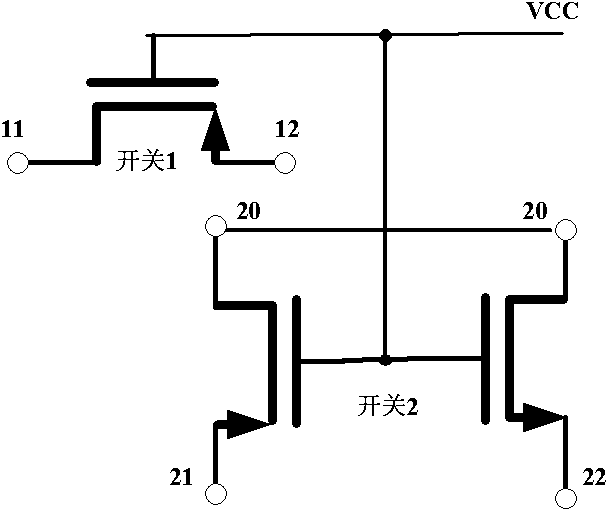
[0022] The semi-active tag structure of the present invention works in two states according to the relationship between the battery voltage value and the voltage value rectified by the rectifier module. figure 1 The structure diagram of the semi-active tag with figure 2 The structure diagram of the switch built by t...


PUM


Abstract

The invention belongs to the field of radio frequency identification and relates to a semi-active label comprising two antennas, a battery, a rectifier module, a digital processing module, a low noise amplifier, a power amplifier, a simulation part, a capacitor, and the like, wherein a radio-frequency signal sent by a reader is received by the first antenna to be used as the input of the rectifier module on the one hand and is connected to the input end of the low noise amplifier on the other hand; the capacitor is in parallel connected between the power supply end and the grounding end of the digital processing module; the output anode of the battery is connected to the power supply end of the low noise amplifier and the power amplifier and the output anode of the rectifier module is connected to the power supply end of the simulation part; and the simulation part is used for demodulating and decoding the received radio-frequency signal and coding and modulating returned data. The label can be automatically converted in active and passive states and can work with long distance and long service life.

Description

technical field [0001] The invention belongs to the field of radio frequency identification and relates to a semi-active RFID tag which can work in two states of active and passive. Background technique [0002] Radio Frequency Identification (RFID) is a non-contact automatic identification technology, which automatically identifies tags through radio frequency signals and can perform two-way data transmission. Different from traditional automatic identification technology, radio frequency identification technology can carry out long-distance, non-line-of-sight identification, and the identification process does not require manual operation, and the process is fast and convenient. Generally speaking, the identification distance of radio frequency identification technology can reach more than tens of meters, it can identify objects in high-speed movement, and it can identify multiple tags at the same time. At the same time, compared with traditional barcodes, RFID tags have ...

Claims


Application Information

Patent Timeline
IPC IPC(8): G06K19/077
Inventor 毛陆虹刘辉田金峰陈力颖张世林
Owner NANTONG HUALONG MICROELECTRONICS
Why Eureka
Try Eureka