Front-end sampling hold and margin amplification circuit of analog-to-digital converter

An analog-to-digital converter, sample-and-hold technology, used in analog-to-digital converters, electrical analog memories, instruments, etc., can solve the problems of limited sampling rate, unfavorable accuracy, limited accuracy, etc., to reduce power consumption and improve linearity. , the effect of improving the accuracy

Inactive Publication Date: 2010-09-15
FUDAN UNIV
View PDF0 Cites 8 Cited by
  • Summary
  • Abstract
  • Description
  • Claims
  • Application Information

AI Technical Summary

Problems solved by technology

Traditional sample-and-hold circuit elimination techniques keep the time constants of the two signal paths consistent by precisely designing the size of capacitors and switches, but factors such as process variations and clock skew still limit the improvement of accuracy
The second solution is to keep the sampled signal after sampling by the sampling capacitor in the sampling phase, and use the sub-analog-to-digital converter for rough quantization, and then perform margin amplification in the next phase[], but this solution requires the original sampling phase Divided into sampling phase and coarse quantization phase, thus limiting further increase in sampling rate
Another method reduces the power consumption of the circuit by sharing the operational amplifier between the front-end sample-and-hold circuit and the first-stage MDAC[], but since the sample-and-hold circuit and the first-stage MDAC each use a set of sampling capacitors, when the first-stage MDAC's sampling capacitor will still introduce various errors when sampling, which is not conducive to the improvement of accuracy

Method used


Image

  • Front-end sampling hold and margin amplification circuit of analog-to-digital converter
  • Front-end sampling hold and margin amplification circuit of analog-to-digital converter
  • Front-end sampling hold and margin amplification circuit of analog-to-digital converter

Examples


Embodiment 1

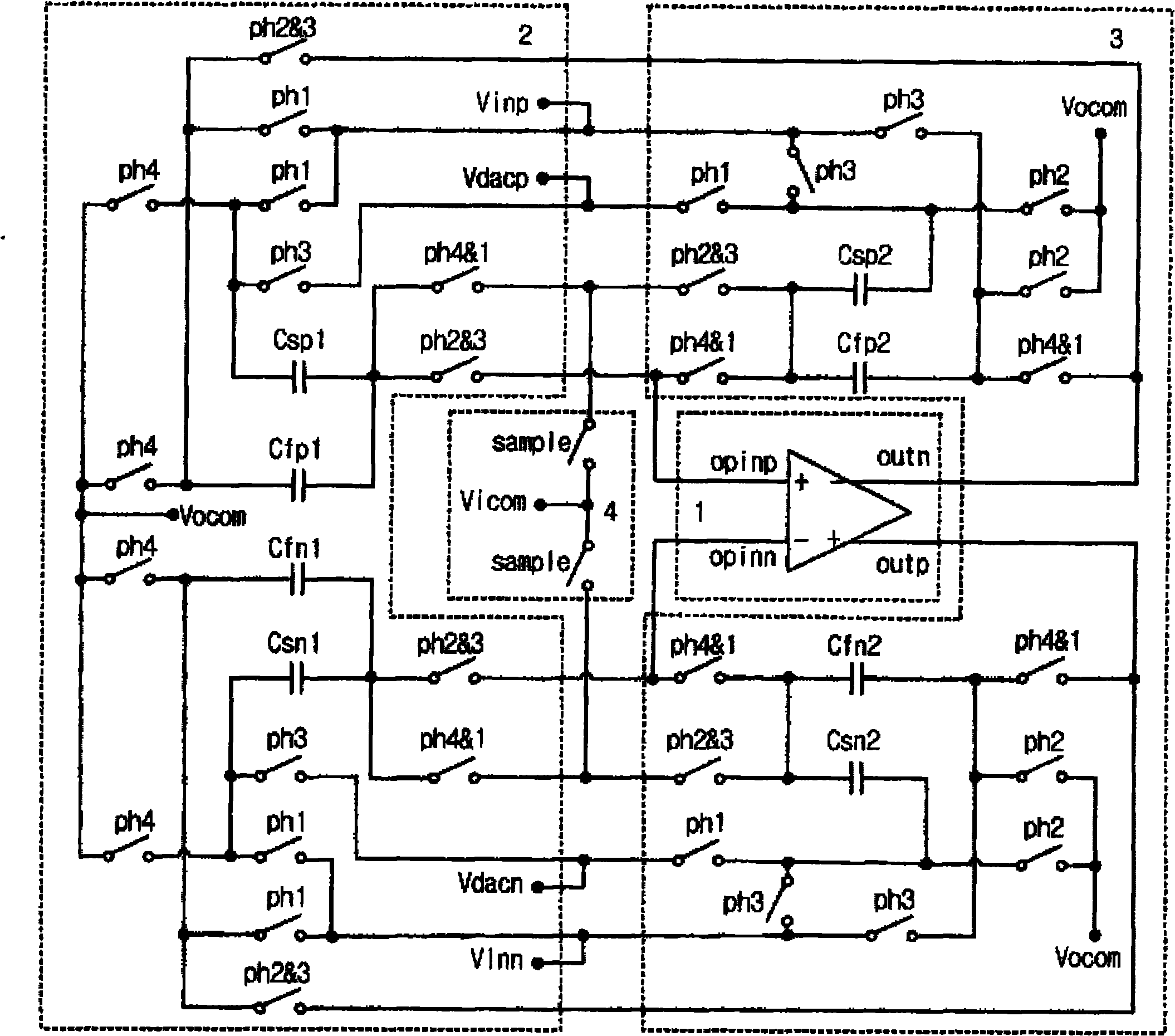
[0027] like figure 1 as shown, figure 1 The present invention provides a schematic structural diagram of a circuit for sample-holding and margin amplification at the front end of a pipelined analog-to-digital converter. The circuit includes an operational amplifier, a first switched capacitor unit, a second switched capacitor unit, and two sampling switches. Wherein, the first switched capacitor unit and the second switched capacitor unit alternate with the operational amplifier and two sampling switches to form a sample-hold and margin amplifier circuit. In the sampling phase, the first switched capacitor unit or the second switched capacitor unit and the two sampling switches sample the current sample, while the second switched capacitor unit or the first switched capacitor unit and the operational amplifier make a margin for the last sampled sample Amplification; in the hold phase, the first switched capacitor unit or the second switched capacitor unit and the operational ...


PUM


Abstract

The invention relates to the technical field of streamline operating analog-to-digital converters, and discloses a front-end sampling hold and margin amplification circuit of an analog-to-digital converter. The circuit comprises an operational amplifier, a first switching capacitor unit, a second switching capacitor unit and two sampling switches, wherein the first switching capacitor unit and the second switching capacitor unit are alternately combined with the operational amplifier and the two sampling switches to form the sampling hold or margin amplification circuit. In a sampling phase, the first switching capacitor unit or the second switching capacitor unit and the two sampling switches sample the current signals, and meanwhile the second switching capacitor unit or the first switching capacitor unit and the operational amplifier amplify the margin (the part of signal removal quantization) of the last sampled signals; and in a holding phase, the first switching capacitor unit or the second switching capacitor unit and the operational amplifier hold the current signals. The circuit can realize the functions of a front-end sampling hold circuit and a fist-stage MDAC circuit of the streamline analog-to-digital converter with lower power consumption at the same time, and improve the precision of the streamline analog-to-digital converter.

Description

technical field [0001] The invention relates to the technical field of pipeline operation analog-to-digital converters, in particular to a circuit for sample-holding and margin amplification at the front end of the pipeline-operation analog-to-digital converter. Background technique [0002] Analog-to-digital converters are an important part of mixed-signal systems, and there are many types of structures. Among them, the pipeline structure is conducive to the trade-off between power consumption, area, speed and accuracy of analog-to-digital converters, so it is widely used. [0003] The traditional pipeline operation ADC front-end requires a precise sample-and-hold circuit[], which inevitably introduces noise and various errors, but its precision requirement is the highest among each pipeline sub-stage, so it Consumes most of the power consumption of the pipelined ADC. [0004] Eliminating the sample-and-hold circuit at the front end of the pipeline ADC greatly reduces the ...

Claims


Application Information

Patent Timeline
Patent Type & Authority Applications(China)
IPC IPC(8): H03M1/12G11C27/02
Inventor 陈奇辉秦亚杰
Owner FUDAN UNIV
Why Eureka
Try Eureka