
Chaotic signal generating circuit

A technology for chaotic signals and generating circuits, applied in electrical components, safety communication devices, digital transmission systems, etc., can solve problems such as algorithm accuracy and capacity bottleneck of logic units, large discreteness of discrete electronic components, and difficulty in circuit design and debugging. , to achieve the effect of easy expansion, strong circuit versatility and simple structure

Active Publication Date: 2010-09-15
盐城市纺织染整产业园实业开发有限公司
View PDF3 Cites 6 Cited by
  • Summary
  • Abstract
  • Description
  • Claims
  • Application Information

AI Technical Summary

Problems solved by technology

[0003] Chua's chaotic circuit is the most typical of many designs. The model of Chua's circuit is realized by electronic circuits composed of capacitors, inductors, resistors and Chua's diodes, which are used to generate double-scroll or multi-scroll chaotic signals. Due to the discrete electronic components Large discreteness brings certain difficulties to circuit design and debugging
At present, there are mainly two types of design methods for chaotic signal generation circuits reported in China: ① Use operational amplifiers, resistors, capacitors and other components to form addition, subtraction, differentiation and integration circuits to realize chaotic signal output. This is composed of discrete components. The analog circuit has large discrete parameters, complex debugging, and poor circuit versatility, which is not conducive to popularization and application; ②Use digital processing technology to discretize the continuous-time dimensionless state equation of the chaotic system, and use FPGA programmable logic devices to realize the algorithm , the chaotic signal is generated through D / A, and it needs to consume a lot of hardware logic resources when implementing the chaotic algorithm with FPGA, so the accuracy of the algorithm and the capacity of the logic unit become the bottleneck of the circuit design

Method used


Image

  • Chaotic signal generating circuit
  • Chaotic signal generating circuit
  • Chaotic signal generating circuit

Examples


Embodiment Construction

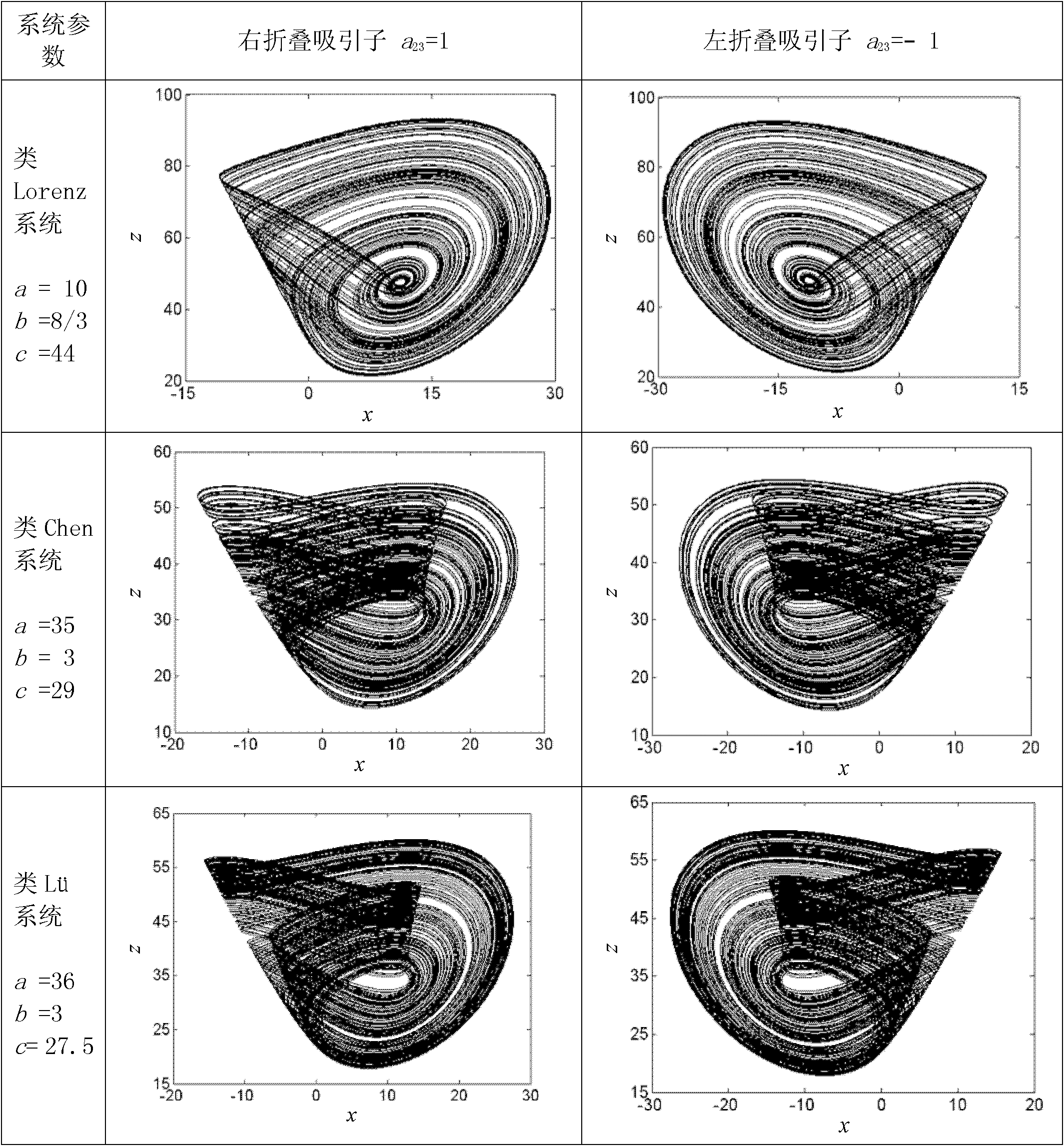
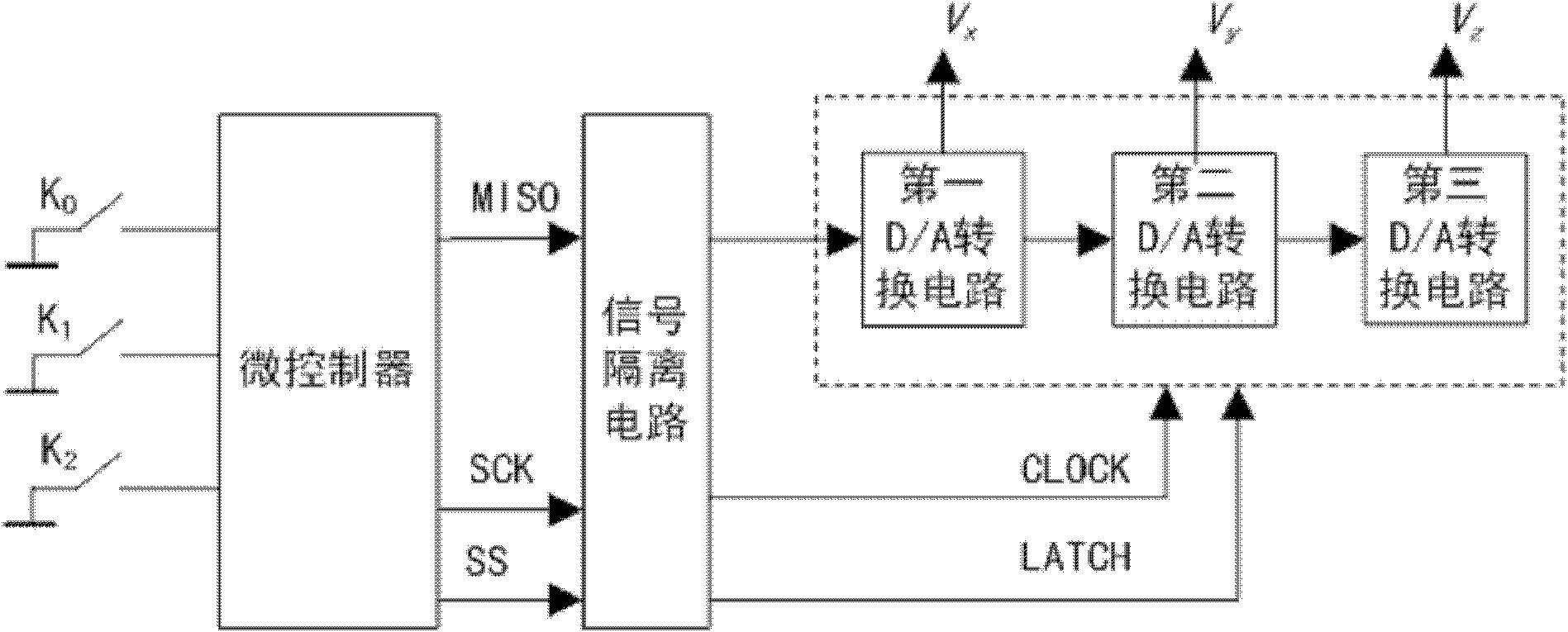
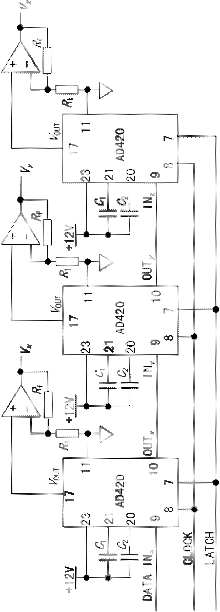
[0021] The chaotic signal generation circuit of this embodiment includes: a microcontroller, a signal isolation circuit, a first D / A conversion circuit, a second D / A conversion circuit and a third D / A conversion circuit.

[0022] Each D / A conversion circuit includes a 16-bit shift register and a 16-bit DAC register, and the shift registers in each D / A conversion circuit are connected in series to form a 48-bit shift register; The serial digital signal MISO output by the SPI interface is sent to the serial data input terminal DATA IN of the first D / A conversion circuit through the signal isolation circuit x The clock signal SCK and the latch control signal SS output by the SPI interface are respectively sent to the clock input terminal CLOCK and the latch control signal input terminal LATCH of each D / A conversion circuit through the signal isolation circuit, so as to realize serial synchronous communication. The SPI interface is a serial peripheral interface.

[0023] The math...


PUM


Abstract

The invention relates to a chaotic signal generating circuit, comprising a microcontroller, a signal isolating circuit, three D / A switching circuits; each D / A switching circuit comprises 16-bit shift registers and 16-bit DAC registers and shift registers in each D / A switching circuit are connected in series to form a 48-bit shift register. Serial digital signals output by an SPI interface of the microcontroller are transmitted to a serial data input terminal of a first D / A switching circuit through the signal isolating circuit; clock signals and latch control signals output by the SPI interface are respectively transmitted to a clock input terminal and a latch control signal input terminal of the D / A switching circuit through the signal isolating circuit. In the invention, based on the chaotic circuit of the microcontroller, the Euler algorithm is adopted to carry out discretization processing on the continuous state equation of the improved generalized Lorenz system; as a result, the operation algorithm which can be appropriately realized by the microcontroller is established and folding directions of chaotic attractors and system operation modes are optional.

Description

technical field [0001] The invention relates to a chaotic signal generating circuit, in particular to an improved generalized Lorenz chaotic signal generating circuit based on a microcontroller. Background technique [0002] Chaos reveals the real law and basic characteristics of nonlinear system motion, and reflects the dynamic behavior of the system. Due to the randomness of chaotic signals, the characteristics of continuous broadband power spectrum, the sensitive dependence of chaotic systems on initial conditions, and the characteristics of being easy to generate and difficult to predict and separate through commonly used time domain and frequency domain processing, chaotic signals are particularly suitable. In the fields of secure communication and information encryption. Therefore, the realization of chaotic signal generating circuits with different chaotic characteristics has long been a hot spot for researchers. The research of chaotic signal generation circuit is ...

Claims


Application Information

Patent Timeline
IPC IPC(8): H04L9/00
Inventor 徐煜明包伯成徐强韩雁
Owner 盐城市纺织染整产业园实业开发有限公司
Learn More