Device for testing residence time distribution (RTD) of material

A residence time and distribution testing technology, applied in measuring devices, material excitation analysis, material analysis through optical means, etc., can solve problems such as melting of adhesives, inconvenient use, fiber detachment, etc., to reduce coupling loss and cost, Compact optical path layout, convenient isolation effect

Inactive Publication Date: 2010-09-22
HANGZHOU EVERFINE PHOTO E INFO
View PDF4 Cites 8 Cited by
  • Summary
  • Abstract
  • Description
  • Claims
  • Application Information

AI Technical Summary

Problems solved by technology

The excitation light beam described in this patent is coupled into the optical fiber through a coupler, the coupling efficiency is low, and the energy consumption is large. In addition, since the optical fiber probe is bonded together by a certain substance and the optical fiber, when the barrel temperature When it is high, it is easy to cause the adhesive to melt and make the probe and optical fiber detach
Moreover, the optical fiber is a fragile device, which is very inconvenient to use

Method used


Image

  • Device for testing residence time distribution (RTD) of material
  • Device for testing residence time distribution (RTD) of material
  • Device for testing residence time distribution (RTD) of material

Examples


Embodiment 1

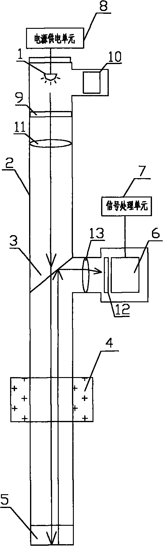
[0022] Such as figure 1 As shown, the material residence time distribution test device includes an excitation light source 1, a light tube 2, a half mirror 3, a heat insulation layer 4, an optical window 5, a fluorescence detector 6, a signal processing unit 7, a power supply unit 8. Excitation light source filter 9, light source lens 11, fluorescent filter 12 and fluorescent lens 13. In this embodiment, the excitation light source 1 is a light emitting diode, and the light tube 2 is a stainless steel cylinder that is opaque and resistant to high temperatures. The power supply unit 8 is a constant current power supply, which drives the light-emitting diodes so that the light-emitting diodes emit a stable excitation beam. A light source detector 10 is provided at the excitation light source 1 to monitor the stability of the excitation light source 1 and compensate the measurement result according to the fluctuation of the excitation light source 1. The excitation light beam pas...

Embodiment 2

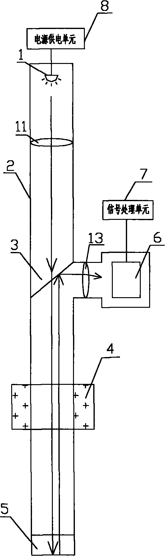
[0025] Such as figure 2 As shown, the material residence time distribution test device includes an excitation light source 1, a light tube 2, a half mirror 3, a heat insulation layer 4, an optical window 5, a fluorescence detector 6, a signal processing unit 7, a power supply unit 8, The light source lens 11 and the fluorescent lens 13. In this embodiment, the excitation light source 1 is a light emitting diode, and the light tube 2 is a stainless steel cylinder that is opaque and resistant to high temperatures. The power supply unit 8 is a constant current power supply, which drives the light-emitting diodes so that the light-emitting diodes emit a stable excitation beam. The excitation light beam passes through the light tube 2, sequentially passes through the light source lens 11, the half mirror 3 and the optical window 5 to reach the material to be measured. The tracer in the tested material is excited by the excitation beam and emits a certain wavelength of fluorescence...

Embodiment 3

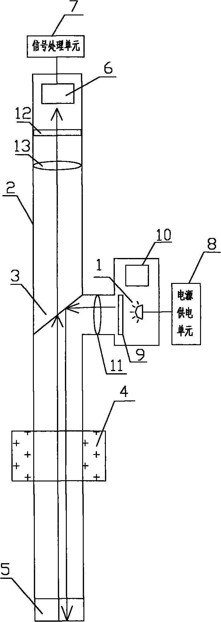
[0028] Such as image 3 As shown, the material residence time distribution test device includes an excitation light source 1, a light tube 2, a half mirror 3, a heat insulation layer 4, an optical window 5, a fluorescence detector 6, a signal processing unit 7, a power supply unit 8. Excitation light source filter 9, light source lens 11, fluorescent filter 12 and fluorescent lens 13. In this embodiment, the excitation light source 1 is a light emitting diode, and the light tube 2 is a stainless steel cylinder that is opaque and resistant to high temperatures. The power supply unit 8 is a constant current power supply, which drives the light-emitting diodes so that the light-emitting diodes emit a stable excitation beam. A light source detector 10 is provided at the excitation light source 1 to monitor the stability of the excitation light source 1 and compensate the measurement result according to the fluctuation of the excitation light source 1. The excitation light beam pa...


PUM


Abstract

The invention discloses a device for testing residence time distribution (RTD) of a material. The device comprises a lighting tube, an optical window, a fluorescence detector, a signal processing unit, an excitation light source, a transflective mirror, a light source power supply unit and the like, wherein the beam emitted from the excitation light source strikes a detected material after passing through the transflective mirror; a tracer in the detected material is excited to emit fluorescence which is transmitted to the fluorescence detector after passing through the transflective mirror; and through the analysis of the signal processing unit, the RTD of the material is calculated. The device for testing the RTD of the material has the advantages of capability of greatly reducing coupling loss and cost because the excitation beam and the fluorescence do not need coupling to an optical fiber in the emitting process, compact light path arrangement, small volume, very convenient use by only being electrically connected with the signal processing unit and the light source power supply unit and capability of conveniently isolating the detected material from the high-temperature and high-pressure environment.

Description

【Technical Field】 [0001] The invention relates to a testing device, in particular to a material residence time distribution testing device. 【Background technique】 [0002] The residence time distribution (RTD) is an important parameter to characterize the material in the reaction, mixing or extrusion process. Residence time refers to the time the material stays in the equipment due to uneven flow rate distribution, backmixing, or non-flowing "dead zone" in the equipment, etc., when the material passes through a continuous operation separation equipment or reaction equipment. The material with different residence time is expressed as the part number of the total material volume is the residence time distribution of the material. It is an important indicator to measure equipment performance. [0003] The currently commonly used method for measuring residence time distribution is stimulus response technology. The stimulus response technique is to inject a tracer into the system, an...

Claims


Application Information

Patent Timeline
Patent Type & Authority Applications(China)
IPC IPC(8): G01N21/64G01N21/01
Inventor 潘建根
Owner HANGZHOU EVERFINE PHOTO E INFO
Why Eureka
Try Eureka