Magnetoplumbate-type permanent magnetic ferrite and manufacturing method thereof

A permanent magnet ferrite and magnetoplumbite technology, applied in the field of permanent magnets, can solve the problems of complicated manufacturing process, high substitution amount of expensive element Co, and high production cost, and achieves good drainage effect, inhibited growth, and molding cycle. short effect

Inactive Publication Date: 2010-09-29
杨宗维
View PDF7 Cites 18 Cited by
  • Summary
  • Abstract
  • Description
  • Claims
  • Application Information

AI Technical Summary

Problems solved by technology

[0007] Patent CN200610169039.1 is in the optimal formula of its embodiment 3 (57 # sample), the substitution amount of the expensive element Co is relatively high
Be 1000 grams of ferric oxide of 99% for every input mass percentage, need to add Co content and be 35.26 grams of cobalt oxide of 74%, its production cost is higher
And its manufacturing process is more complicated than that of conventional magnetoplumbite permanent magnet ferrite

Method used


Image

  • Magnetoplumbate-type permanent magnetic ferrite and manufacturing method thereof
  • Magnetoplumbate-type permanent magnetic ferrite and manufacturing method thereof
  • Magnetoplumbate-type permanent magnetic ferrite and manufacturing method thereof

Examples


Embodiment 1

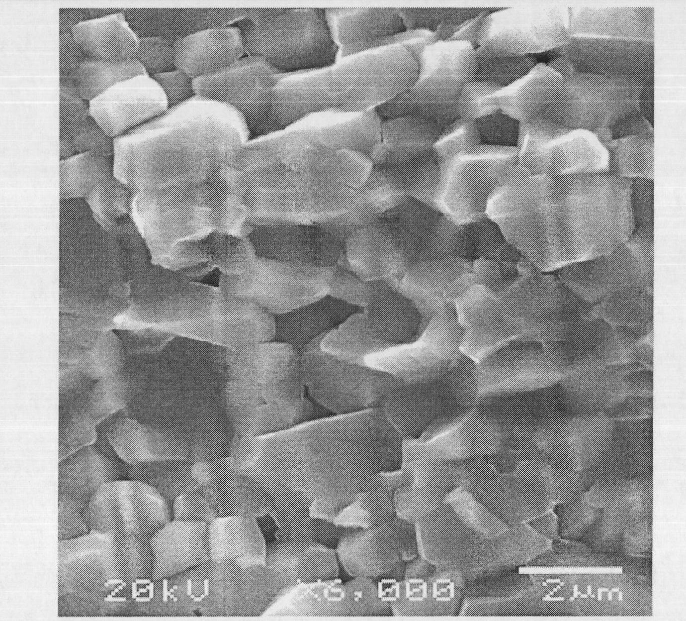
[0044] Prepare Fe with a mass fraction of more than 99% 2 o 3 powder, its SiO 2 The mass fraction of ≤0.015%, its chloride (Cl - ) mass fraction ≤ 0.15%; its average particle size is 0.95 μm; prepare SrCO with mass fraction above 98% 3 Powder, the average particle size is 2 μm; the mass fraction is more than 98.5% CaCO 3 Powder, the average particle size of which is 4 μm; the mass fraction is more than 99% La 2 o 3 Powder with an average particle size of 4 μm; cobalt oxide powder containing more than 72% Co, with an average particle size of 2.7 μm; more than 99% ZrO 2 Powder with an average particle size of 1 μm. According to (1-x-y)CaO xSrO (y / 2)R 2 o 3 ·(n-z / 2-m / 2)Fe 2 o 3 ·zMO·mZrO 2 The addition amount of each main raw material was calculated, wherein x=0.1, y=0.6, z=0.25, m=0.04, n=4.9. Then the compounds containing each element are accurately weighed according to the calculated amount, and the main raw materials are wet mixed. Its mixing time was 4 hours. T...

Embodiment 2

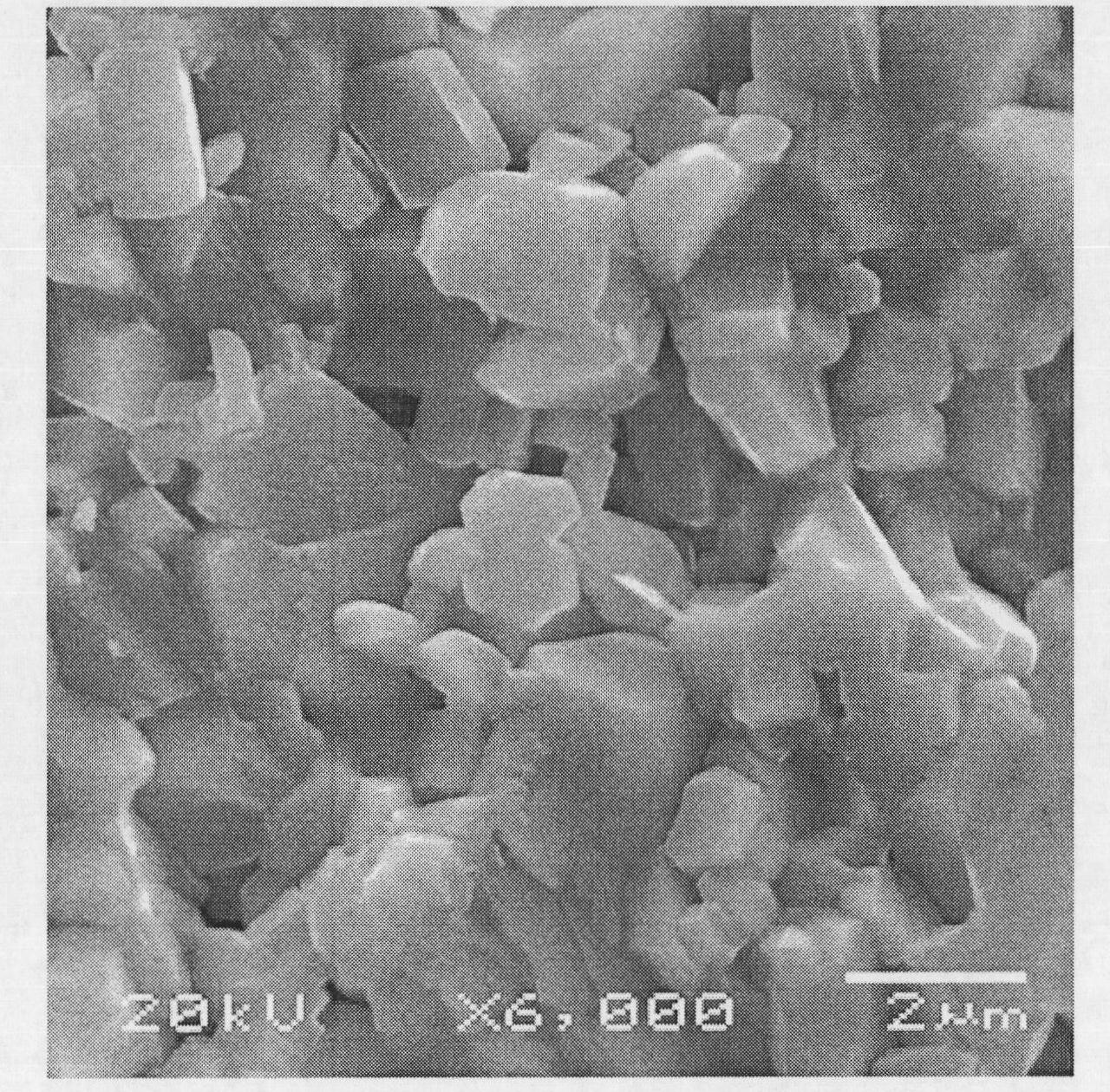
[0046] Adopt the calcined powder in embodiment 1, add 0.6% calcium gluconate as dispersant when finely pulverizing, all the other are identical with embodiment 1. Its magnetic properties are shown in Table 1, and the microstructure of the obtained magnet is as follows figure 2 shown. The SEM analysis of the magnet section shows that the crystal structure is relatively loose, the grain size is not uniform, the porosity is 1.1%, and no abnormal growth grains are seen.

Embodiment 3

[0048] Adopt the calcined powder in embodiment 1, do not add dispersant when pulverizing finely, all the other are the same as embodiment 1. Its magnetic properties are listed in Table 1.


PUM

PropertyMeasurementUnit
particle sizeaaaaaaaaaa

Abstract

The invention relates to a magnetoplumbate-type permanent magnetic ferrite and a manufacturing method thereof, which relate to the field of the permanent magnet. Main component of the magnetoplumbate-type permanent magnetic ferrite is expressed by the following formula: (1-x-y)Ca0.xSrO.(y / 2)R2O3.(n-z / 2-m / 2)Fe2O3.zMO.MzrO2, wherein R is of at least one element of La, Nd and Pr and contains La, M is selected from at least one element of Co, Zn, Ni, Mn and Cu and contains Co, and x, y, z, m and n respectively indicating the addition ratio of each main metal element calculated at mol. By adopting optimized formula and process design and adding less Zr element, the Zr element is introduced into ferrite lattice during the pre-burning process so as to inhibit the growth of abnormal crystal particle and to reduce the pores; moreover, N(CH2CH2OH)3 dispersing agent is particularly added, the appearance of the powder particles is effectively controlled, so the obtained crystal particles are moreuniform, the arrangement of the crystal structure is more compact, and the permanent magnetic ferrite material is obtained under the condition that substitute of the Co element is not high.

Description

Technical field: [0001] The invention relates to a magnetoplumbite type permanent magnet ferrite and a manufacturing method thereof, which relate to the field of permanent magnets, in particular to sintered permanent magnet ferrite. Background technique: [0002] Ferrite is a compound composed of divalent cation metal oxide and ferric iron. Permanent ferrite material is a functional material that generates a magnetic field. High-performance permanent ferrite plays an important role in the electronics industry, information industry, motorcycles, electric tools, automobile industry and other industries. The widely used ferrite material is Sr ferrite (SrFe 12 o 19 ) and Ba ferrite (BaFe 12 o 19 ), these ferrites are made of iron oxide and Sr or Ba carbonate as raw materials, and are manufactured by powder metallurgy. The final magnetic properties of the obtained magnets are generally determined by the remanence Br, intrinsic coercive force H CJ to measure. In recent year...

Claims


Application Information

Patent Timeline
Patent Type & Authority Applications(China)
IPC IPC(8): C04B35/057C04B35/622
Inventor 向桥春王自敏杨宗维
Owner 杨宗维
Why Eureka
Try Eureka