Optical waveguide immunosensor and detection method thereof

A technology of immune sensor and detection method, which is applied in the field of optical guided wave immune sensor and its detection, can solve the problems of small refractive index, limited device sensitivity, long interference arm, etc., and achieve simple structure, sensitive immune response detection, and good application prospects Effect

Inactive Publication Date: 2010-09-29
SUZHOU INST OF BIOMEDICAL ENG & TECH
View PDF8 Cites 19 Cited by
  • Summary
  • Abstract
  • Description
  • Claims
  • Application Information

AI Technical Summary

Problems solved by technology

No excitation light source is required, so background interference from spontaneous emission is avoided, but very sensitive detectors are required
[0008] (2) Unmarked type
However, the refractive ind...

Method used


Image

  • Optical waveguide immunosensor and detection method thereof
  • Optical waveguide immunosensor and detection method thereof
  • Optical waveguide immunosensor and detection method thereof

Examples


Embodiment Construction

[0045] The technical implementation process of the present invention will be further described below in conjunction with the accompanying drawings and embodiments.

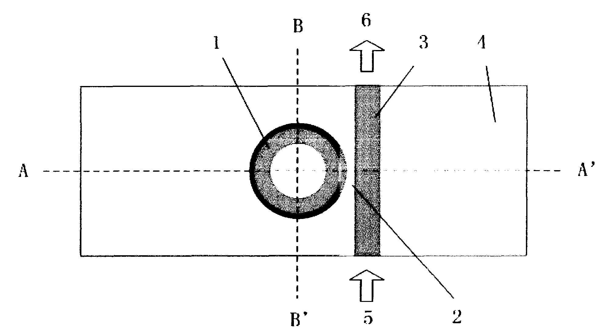
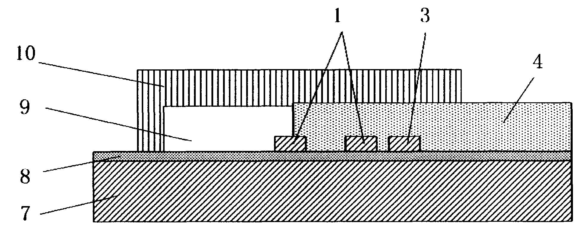
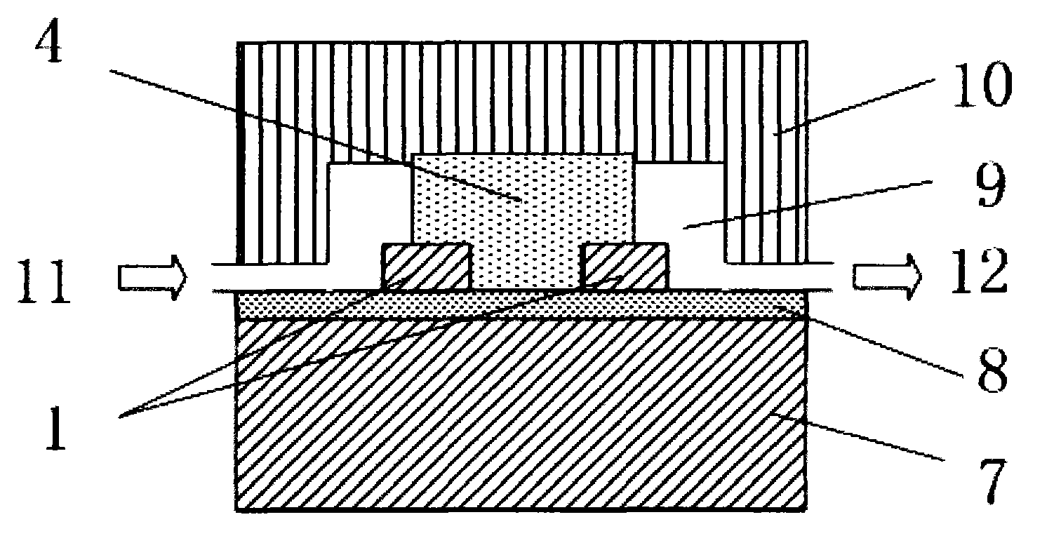
[0046] see figure 1 , figure 2 , image 3 , Figure 4 As shown, an optical waveguide immune sensor includes a sensor substrate 7, an immune reaction pool 9 is arranged on the sensor substrate 7, and the immune reaction pool 9 has a liquid inlet 11 and a liquid outlet 12, so An upper cover layer 10 is arranged above the immune reaction pool 9, an optical waveguide resonant cavity 1 is arranged at the bottom of the immune reaction pool 9, and an optical waveguide upper confinement layer 4 is arranged above the optical waveguide resonant cavity 1. An optical waveguide lower confinement layer 8 is arranged below the waveguide resonant cavity 1, and there is a coupling region 2 between the optical waveguide upper confinement layer 4 and the optical waveguide lower confinement layer 8, and the optical waveguide reso...


PUM

PropertyMeasurementUnit
Diameteraaaaaaaaaa

Abstract

The invention discloses an optical waveguide immunosensor and a detection method thereof. The optical waveguide immunosensor basically comprises an optical waveguide resonator cavity, a magnetic needle and an immunologic reaction tank. The method comprises the following steps of: carrying out surface specificity modification to nano magnetic particles; capturing a substance to be detected by utilizing an antibody-antigen reaction; orderly limiting the nano magnetic particles on the surface of the circular or disc-shaped optical waveguide resonator cavity by utilizing the magnetic needle; sensing refraction index change before and after an immunologic reaction by utilizing an evanescent field; and analyzing corresponding resonance spectrum change to acquire the content of the substance to be detected in a sample. The optical waveguide immunosensor has simple structure. Based on the circular or disc-shaped optical waveguide resonator cavity with compact structure, the nano particles after immunologic specificity modification are absorbed to the optical waveguide surface by the magnetic needle to measure the offset of a resonance frequency and accurately and sensitively detect the immunologic reaction, and the device can be repeatedly used so that the invention has favorable application prospects.

Description

technical field [0001] The invention relates to a sensor, in particular to an optical guided wave immune sensor and a detection method thereof. Background technique [0002] With the continuous rapid growth of the economy, the living standards of the people have improved rapidly, the process of urbanization has continued to accelerate, and the living environment has continued to change. New environmental conditions have led to the emergence of new diseases and disease variants, which have brought new pressures to our country's medical and health departments. At the same time, traditional major diseases such as AIDS, tuberculosis and hepatitis have not been effectively curbed and are still endangering the health of the people. In order to protect health and do a good job in prevention and treatment, it is urgent to quickly and accurately detect potential biological substances in the human body, the surrounding environment, and food that may affect human health at the molecul...

Claims


Application Information

Patent Timeline
IPC IPC(8): G01N33/53G01N21/25
Inventor 王帆崔锦江姜琛昱王策檀慧明
Owner SUZHOU INST OF BIOMEDICAL ENG & TECH
Why Eureka
Try Eureka