Ageing predetermination and overspeed delay testing bifunctional system and method thereof

A technology of aging prediction and delay testing, which is applied in the field of semiconductor technology and can solve the problems of waste of hardware circuit resources, discarding, etc.

Active Publication Date: 2010-10-06
INST OF COMPUTING TECH CHINESE ACAD OF SCI
View PDF5 Cites 13 Cited by
  • Summary
  • Abstract
  • Description
  • Claims
  • Application Information

AI Technical Summary

Problems solved by technology

But this approach causes a waste of hardware circuit resources
Traditional hardware circuits for ultra-speed latency te

Method used


Image

  • Ageing predetermination and overspeed delay testing bifunctional system and method thereof
  • Ageing predetermination and overspeed delay testing bifunctional system and method thereof
  • Ageing predetermination and overspeed delay testing bifunctional system and method thereof

Examples


specific Embodiment

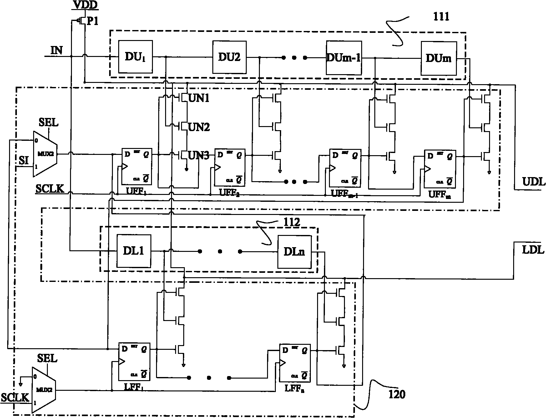
[0128] All scannable flip-flops connected to the upper delay sub-module and the lower delay sub-module are cascaded to form a circular shift register.

[0129] When the initial state of the aging prediction mode is moved into the first control vector, the first control vector is a specific two-hot code; when the first state of the overspeed delay test mode is moved into the second control vector, the second control vector is another A specific two-hot code.

[0130] It is shifted into the circular shift register under the control of SCLK (scanning clock) signal. Since only two bits of this specific two-hot code are 1 and the other bits are all 0, only one output terminal of the scannable flip-flops connected to the upper delay sub-module and the lower delay sub-module is 1 and the other The outputs of the flip-flops are all 0s. Therefore, at the same time, only one group of stacked NMOS transistors in the upper and lower delay sub-modules are all in the conduction state. Th...

specific Embodiment approach

[0153] The aging effect sensor is in a stable state and a capture state in the aging prediction working mode;

[0154] The aging effect sensor is further used to switch between the stable state and the capture state according to the response capture clock signal, the response of the target circuit is not captured in the stable state, the output signal is kept at a low level, and the In the capture state, the response of the circuit is captured within the capture interval, and if the response of the target circuit jumps within the capture interval, the output signal will change from low level to high level to generate an up transition as an alarm signal.

[0155] The structure of the circuit response capturing module in one embodiment is as follows Figure 5 shown.

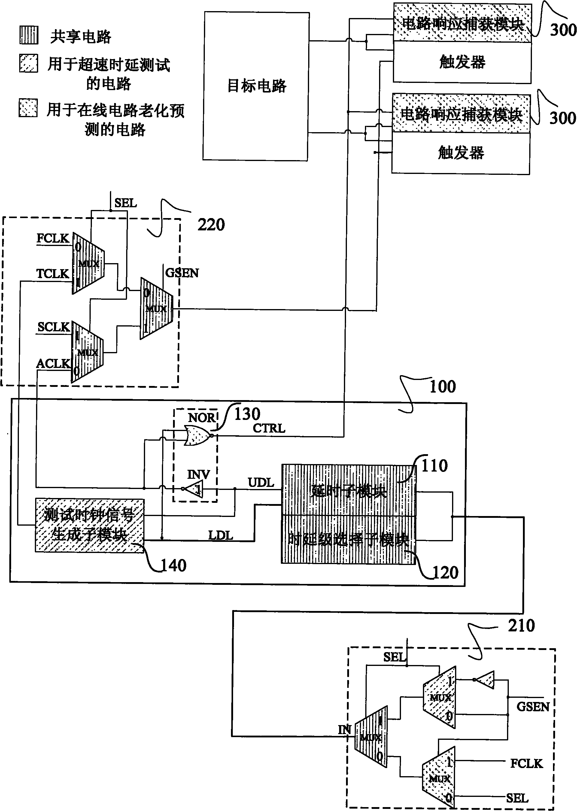
[0156] In the normal working mode, since the output signal LDL of the down-delay sub-module 112 in the clock generation module 100 is kept at a high level, the CTRL signal is kept at a low level. The low level o...


PUM


Abstract

The invention relates to an ageing predetermination and overspeed delay testing bifunctional system and method thereof. The system comprises a clock signal generating module, an operating mode and clock selecting module and a circuit response capturing module; wherein the clock signal generating module is used for generating a programmable clock signal according to a first control vector and generating a plurality of test clock signals according to a second control vector; the operating mode and clock selecting module is used for determining the operating mode of the system according to a control signal, selecting a signal among the programmable clock signal, a system functional clock signal and a test clock signal and inputting the selected signal to the system clock tree of a target circuit to carry out operation in corresponding operating mode, and the operating modes include normal operating mode, ageing predetermination mode and overspeed delay testing mode; and the circuit response capturing module is used for capturing the response of the target circuit in the capturing interval when the current mode is the ageing predetermination mode and is also used for generating a corresponding alarm signal according to the fact that whether signal step appears in the capturing interval. The invention can carry out overspeed delay testing and online circuit ageing predetermination.

Description

technical field [0001] The invention relates to the technical field of semiconductor technology, in particular to a dual-function system and method for aging prediction and overspeed delay test. Background technique [0002] As process technology enters the nanometer scale, transistor feature sizes continue to decrease. In this case, NBTI (Negative Bias Temperature Instability), an aging effect on PMOS transistors, becomes the primary factor affecting circuit lifetime reliability. The NBTI effect will increase the delay of the circuit as the circuit is used for a long time, thereby causing a timing violation problem in the circuit. Some research work has shown that in the worst operating environment, the NBTI effect can lead to a 20% increase in circuit delay within 10 years. Since circuit aging is a relatively slow process, online circuit aging prediction is an effective method to predict circuit failure caused by aging effects. The on-line circuit aging predictor captur...

Claims


Application Information

Patent Timeline
IPC IPC(8): G01R31/28
Inventor 靳松韩银和李华伟李晓维
Owner INST OF COMPUTING TECH CHINESE ACAD OF SCI
Why Eureka
Try Eureka