Pressure-sensitive optical cable with armor layer

An armored layer and pressure-sensitive technology, which is applied in the field of optical cables for pressure sensing, can solve problems such as inability to adapt to environmental conditions, poor lateral pressure resistance and tensile resistance, and achieve convenient use, improve lateral pressure resistance, and prevent erosion effect

Inactive Publication Date: 2010-10-06
XIAN JINHE OPTICAL TECH
View PDF0 Cites 7 Cited by
  • Summary
  • Abstract
  • Description
  • Claims
  • Application Information

AI Technical Summary

Problems solved by technology

[0004] The structure of the existing pressure-sensitive optical cable is shown in the diagram figure 1 , the pressure-sensitive optical cable is a thin fiber 2 helically wound on the signal optical fiber 1, the outermost layer is the sheath of the optical cable, the outer diameter of the optical cable is about 0.8mm, the structure is simple, and the resistance to lateral pressure and tensile force performance Poor, can not adapt to harsh outdoor environmental conditions, so it is limited to use in special environmental conditions

Method used


Image

  • Pressure-sensitive optical cable with armor layer
  • Pressure-sensitive optical cable with armor layer
  • Pressure-sensitive optical cable with armor layer

Examples


Embodiment 1

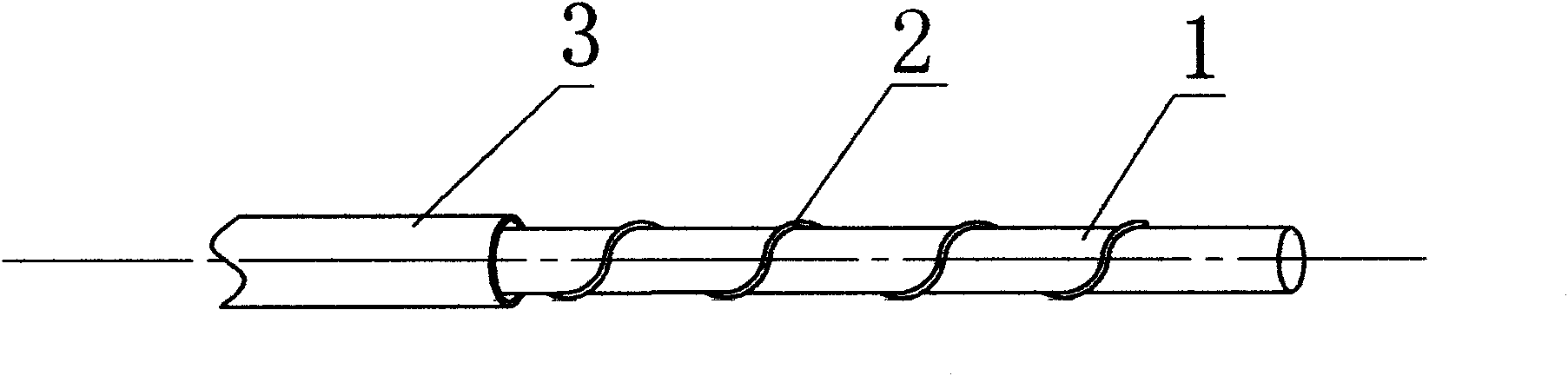
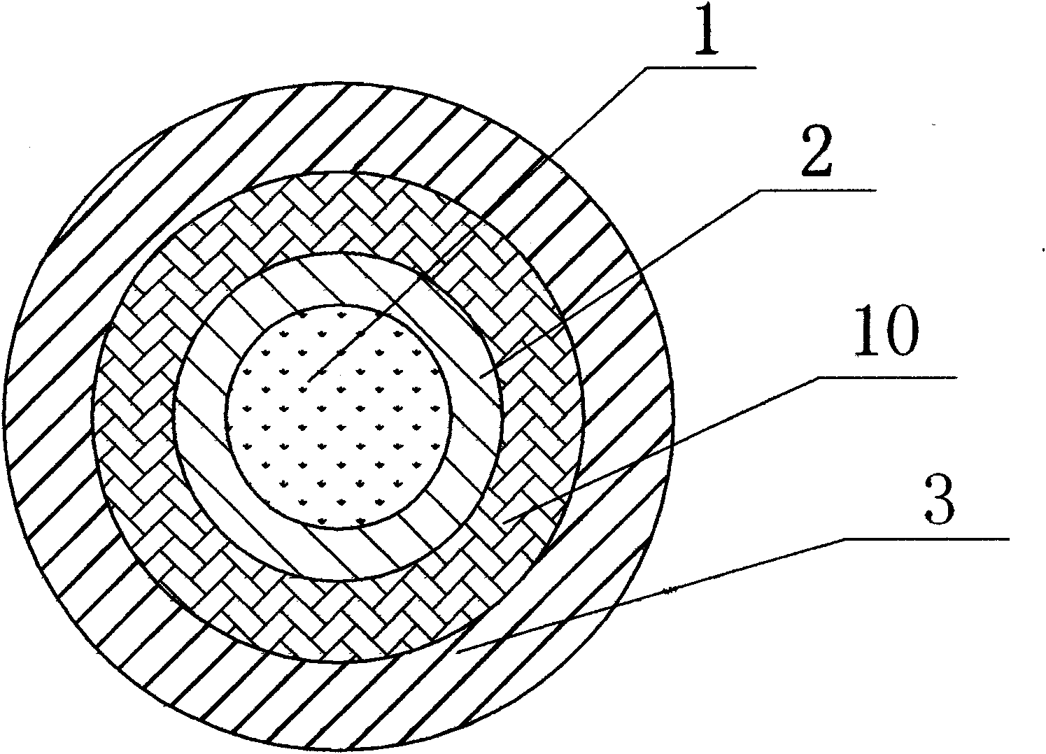
[0031] Such as figure 2 As shown, the present invention includes a signal optical fiber 1 and a fiber filament 2 helically wound on the signal optical fiber, and an armor layer 10 and an outer sheath 3 are arranged on the periphery in turn. During actual manufacturing, the voids inside the outer sheath 3 are filled with water-blocking materials.

[0032] In this embodiment, the outer sheath 3 is deformed under external pressure, thereby transmitting the external force to the fiber filament 2 helically wound on the signal optical fiber, and under the action of pressure, the fiber filament 2 causes the signal optical fiber 1 to bend and deform , thereby changing the bending loss of the signal optical fiber 1 , thereby realizing the modulation of the transmission light intensity in the signal optical fiber 1 . In this way, the pressure signal is converted into an optical signal and transmitted through the signal optical fiber 1 to realize remote measurement or distributed measu...

Embodiment 2

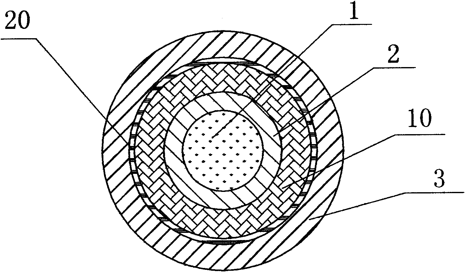
[0035] Such as image 3 As shown, in this embodiment, the difference from Embodiment 1 is that there is a film material layer between the outer sheath 3 and the armor layer 10, which can prevent the pressure-sensitive optical cable from maintaining the pressure-sensitive optical cable during processing and use. Roundness. In this embodiment, the structures, connections and working principles of other parts are the same as those in Embodiment 1.

Embodiment 3

[0037] Such as Figure 4 As shown, in this embodiment, the difference from Embodiment 1 is that there are two tensile elements inside the outer sheath 3 near the armor layer 10, which can be steel wires or FRP rods, to strengthen the compression force. Tensile properties of sensitive optical cables. In this embodiment, the structures, connections and working principles of other parts are the same as those in Embodiment 1.


PUM


Abstract

The invention discloses a pressure-sensitive optical cable with armor layer, which takes a signal optical fiber and fiber yarns spirally wound on the signal optical fiber and which is peripherally provided with an armor layer and an outer protective layer in sequence. As pressure is applied to the pressure-sensitive optical cable, the fiber yarns spirally wound on the signal optical fiber lead the signal optical fiber to bending deformation in order to change the bending loss of the signal optical fiber. As a result, pressure signals are converted into optical signals which are then transmitted via the signal optical fiber to achieve the purpose of remote measurement. The armor layer made of fine fiber material has the characteristics of excellent bending flexibility, facilitating manufacture, storage, transportation and use of the pressure-sensitive optical cable, similarity to common optical cables, being capable of remarkably reducing manufacturing and use costs, and having no impact on pressure detection. The pressure-sensitive optical cable has simple structure, reasonable design, convenient processing and manufacturing, diversified using ways, high sensitivity and good using effect, and distributive pressure measurement can be realized by means of optical time domain reflectometer or other measurement instruments.

Description

technical field [0001] The invention relates to an optical cable for pressure sensing, in particular to an optical cable with an armor layer which utilizes the microbend loss of an optical fiber for pressure sensing. Background technique [0002] There are many methods for measuring pressure in traditional pressure sensors, such as strain gauge measurement, optical measurement, Hall effect measurement, grating ruler measurement and so on. However, many current measurement methods are not conducive to remote measurement and monitoring, especially due to the interference of strong external electrical signals, serious distortion of remote transmission, complex measurement mechanism, poor reliability, and unfavorable maintenance. In addition, for flammable and explosive environments, all methods of using electrical measurement are not suitable, because any spark may cause serious fire or explosion accidents, causing immeasurable losses. The optical fiber stress sensor has many ...

Claims


Application Information

Patent Timeline
Patent Type & Authority Applications(China)
IPC IPC(8): G02B6/44G01L1/24
Inventor 杜兵杜蔚杜迎涛
Owner XIAN JINHE OPTICAL TECH
Why Eureka
Try Eureka