Electromagnetic riveting press suitable for large-diameter rivets and press riveting method thereof

A riveting machine and large-diameter technology, applied in the field of riveting, can solve the problems of high operating level requirements for operators, difficulty in strictly controlling the amount of interference, and damage to composite material installation, so as to improve the stability of riveting quality, improve riveting ability and process Flexibility, the effect of avoiding installation damage

Inactive Publication Date: 2010-10-13
HARBIN INST OF TECH
View PDF4 Cites 20 Cited by
  • Summary
  • Abstract
  • Description
  • Claims
  • Application Information

AI Technical Summary

Problems solved by technology

[0007] The object of the present invention is to provide an electromagnetic riveting machine suitable for large-diameter rivets and its riveting method, so as to solve the problem of riveting with large-diameter rivets for composite material structures. The use of hammer riveting and pressure riveting is easy to cause installation damage and breakdown of composite materials. layer and other defects, and it is difficult to strictly control the amount of interference and the use of electromagnetic riveting requires a high level of operation of the operator.

Method used


Image

  • Electromagnetic riveting press suitable for large-diameter rivets and press riveting method thereof
  • Electromagnetic riveting press suitable for large-diameter rivets and press riveting method thereof
  • Electromagnetic riveting press suitable for large-diameter rivets and press riveting method thereof

Examples


specific Embodiment approach 1

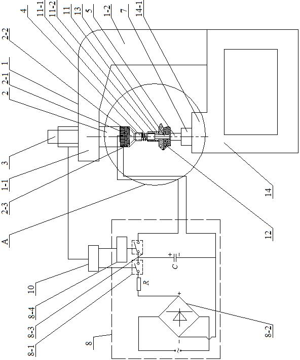
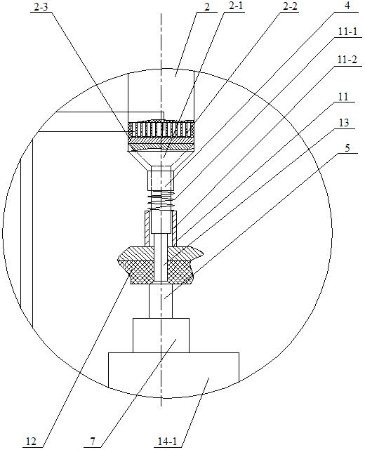
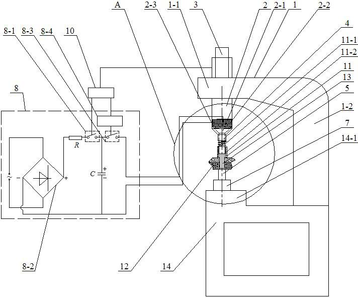
[0013] Specific implementation mode one: combine figure 1 and figure 2 Describe this embodiment, an electromagnetic riveting machine suitable for large-diameter rivets in this embodiment consists of a bent upper arm 1, an electromagnetic riveting gun 2, a power source 3 for riveting gun stroke control, an upper riveting die 4, and a lower riveting die 5 , workbench 7, low-voltage electromagnetic riveting device 8, control box 10, spring compactor 11 and base 14; An integrated horizontal arm 1-1 and a vertical arm 1-2 are formed. The lower end of the vertical arm 1-2 is fixedly connected to the upper end surface of the base 14, and the upper end surface of the base 14 is provided with a raised platform 14-1. 7 is fixed on the protruding platform 14-1, the upper riveting die 4 and the lower riveting die 5 are set coaxially from top to bottom, and the lower riveting die 5 is set on the workbench 7, and the die sleeve 11-2 is set on the upper riveting die On the mold 4 and the ...

specific Embodiment approach 2

[0015] Specific implementation mode two: combination figure 1Describe this embodiment, the low-voltage electromagnetic riveting device 8 of this embodiment consists of an electromagnetic riveting charging switch 8-1, a capacitor bank C, a current limiting resistor R, a rectifier 8-2, a high-frequency thyristor discharge switch 8-3 and a high-voltage pulse generator 8-4; the two ends of the power supply are respectively connected to the two AC voltage input terminals of the rectifier 8-2, the positive output terminal of the DC voltage of the rectifier 8-2 is connected to one end of the current limiting resistor R, and the other end of the current limiting resistor R It is connected with one end of the electromagnetic riveting charging switch 8-1, and the other end of the electromagnetic riveting charging switch 8-1 is respectively connected with one end of the high-frequency thyristor discharge switch 8-3 and the positive end of the capacitor bank C, and the high-frequency thyri...

specific Embodiment approach 3

[0016] Specific embodiment three, combine figure 1 Describe this embodiment mode, a kind of pressure riveting method suitable for large-diameter rivets in this embodiment mode is realized by the following steps: 1. Select the upper riveting die 4 and the lower riveting die 5 according to the structural form of the structural assembly 12 to be riveted, and select the rivet 13 Large-diameter titanium alloy rivets or large-diameter aluminum alloy rivets, the head of the rivet 13 is in the shape of a countersunk or semi-round head, the diameter of the large-diameter titanium alloy rivet is Ф2-Ф6mm, and the diameter of the large-diameter aluminum alloy rivet is Ф4-Ф10mm; 1. The upper end surface of the upper riveting die 4 is attached to or integrated with the lower end face of the stress wave modulator 2-1 of the electromagnetic riveting gun 2, and the lower riveting die 5 is placed on the workbench 7; Three, connect the electromagnetic pressure The riveting gun stroke of the rive...


PUM

PropertyMeasurementUnit
diameteraaaaaaaaaa
diameteraaaaaaaaaa
diameteraaaaaaaaaa

Abstract

The invention discloses an electromagnetic riveting press suitable for large-diameter rivets and a press riveting method thereof, and relates to an electromagnetic riveting press and a press riveting method thereof. A composite structure is riveted by adopting the large-diameter rivets, and the problem of interference quantity and higher electromagnetic riveting requirement operation level are difficultly controlled by adopting hammer riveting and press riveting. An upper riveting die and a stress wave modulator of an electromagnetic riveting gun are jointed or manufactured into a whole; the electromagnetic riveting gun is arranged on a slipway on a horizontal arm; a riveting gun stroke control power source is connected with a control box; the control box is connected with a charge control signal input end of a low-voltage electromagnetic riveting device and a high-voltage pulse generator; the high-voltage pulse generator is connected with a discharge control signal input end of the low-voltage electromagnetic riveting device; positive and negative output ends of discharge signals are connected with two ends of a coil of the electromagnetic riveting gun; and the riveting gun stroke control power source drives the electromagnetic riveting gun to move downwards, a capacitor bank is charged and discharged, and a driving plate is subjected to the axial downward pulse loading effect so that an extended part of a nail bar forms an upset head. The electromagnetic riveting press is used for riveting structural members by the large-diameter rivets.

Description

technical field [0001] The invention relates to an electromagnetic riveting machine and a riveting method thereof, belonging to the technical field of riveting. Background technique [0002] Riveting is a mechanical connection technology widely used in the manufacturing fields of aerospace, automobiles, electronic appliances, etc. It mainly includes hammer riveting, electromagnetic riveting and pressure riveting. [0003] Hammer riveting is a commonly used riveting method. When riveting, use the impact force to hit the head of the rivet rod several times continuously, so that the rivet material flows in the radial direction, forming the riveted head of the connected parts. The characteristics of hammer riveting are: the required impact force is relatively large; the riveted part and the riveting tool have a large vibration; the force on the head of the rivet rod is unbalanced, and the product quality is unstable; The organizational structure of the head material of the riv...

Claims


Application Information

Patent Timeline
Patent Type & Authority Applications(China)
IPC IPC(8): B21J15/24B21J15/38
CPCB21J15/12
Inventor 于海平李春峰武伟让
Owner HARBIN INST OF TECH
Why Eureka
Try Eureka