Electronic ballast for operating at least two different types of discharge lamps

A technology of electronic ballasts and discharge lamps, applied in the direction of electric light sources, electrical components, lighting devices, etc., can solve problems such as radio interference, and achieve the effect of reducing loss and small distance

Inactive Publication Date: 2014-12-10
OSRAM GMBH
View PDF6 Cites 0 Cited by
  • Summary
  • Abstract
  • Description
  • Claims
  • Application Information

AI Technical Summary

Problems solved by technology

The greater the difference between the grid input voltage and the intermediate circuit voltage, the higher the switching frequency of the step-up switch, which creates problems with respect to radio interference

Method used


Image

  • Electronic ballast for operating at least two different types of discharge lamps
  • Electronic ballast for operating at least two different types of discharge lamps
  • Electronic ballast for operating at least two different types of discharge lamps

Examples


Embodiment Construction

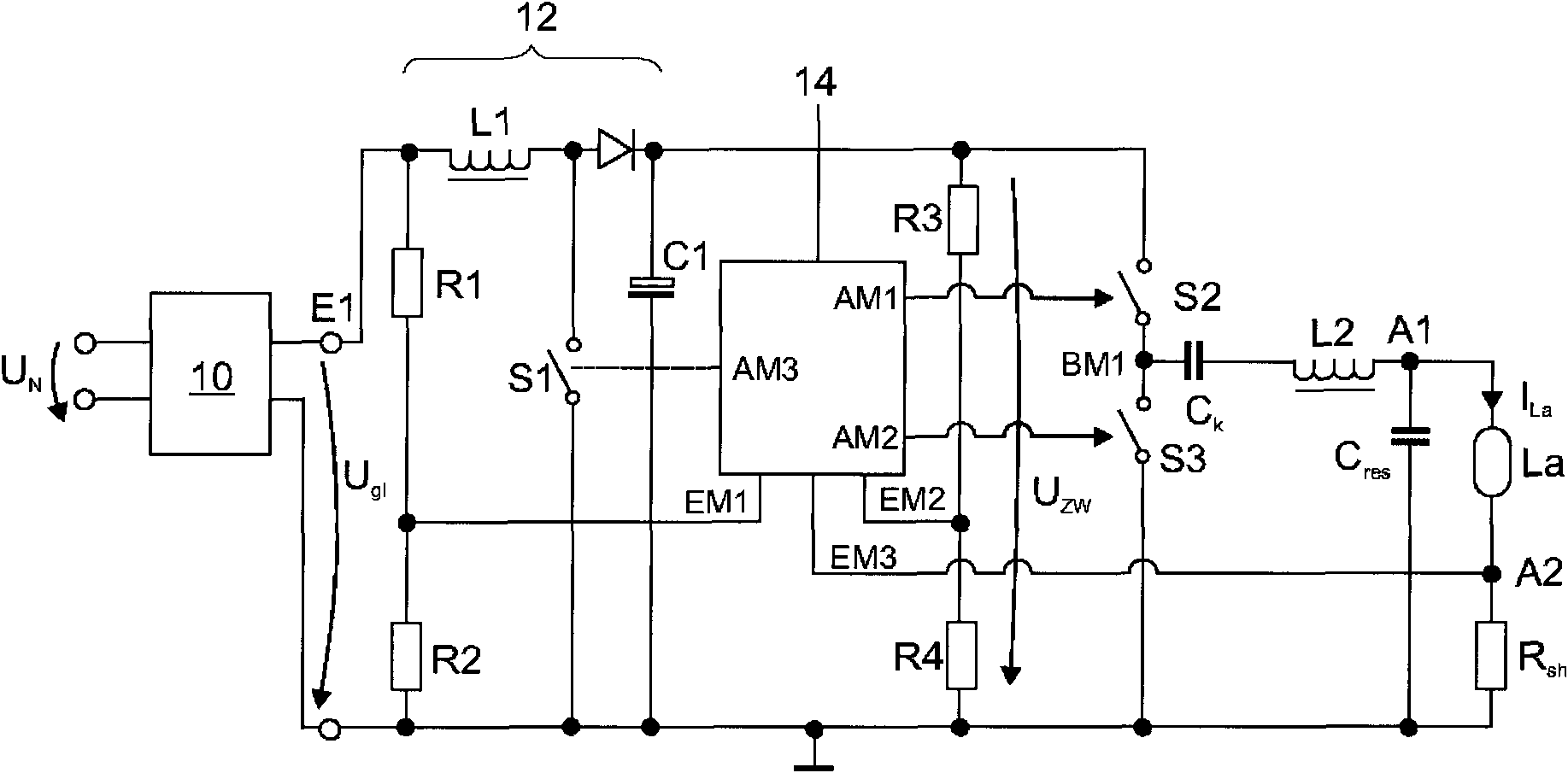
[0015] figure 1 An embodiment of an electronic ballast according to the invention is shown in a schematic diagram. The ballast comprises an input with a first input terminal and a second input terminal, between which the grid voltage U is applied N . A rectifier 10 is coupled to the input and provides a voltage U at the output E1, E2 of this rectifier g1 , which corresponds to the rectified grid voltage U N . Voltage U g1 with peak U peak . Following the rectifier 10 is a boost converter 12 comprising a boost inductor L1 , a boost diode D1 and a boost switch S1 . It is also possible to connect the DC voltage directly to the input of the boost converter 12, as will be apparent to those skilled in the art. Thus, the electronic ballast according to the present invention will work equally well.

[0016] The voltage provided at the output of the boost converter 12 and stabilized by means of the capacitor C1 is the so-called intermediate circuit voltage U Zw . A bridge ci...


PUM


Abstract

#CMT# # / CMT# The device has an input unit provided with two input connectors (E1) for connection of direct current supply voltage unit (Un). Voltage measuring devices (R1-R4) are provided for measuring voltage between input connectors and output connectors of a boost-converter (12). A microcontroller (14) is provided with two inputs (EM1, EM2), which are coupled with voltage measuring devices. The micro-controller is designed such that voltage (Uzw) between output connectors of the converter is controlled to a value, which depends upon a value of voltage (Ugl) between the input connectors of converter. #CMT#USE : # / CMT# Electronic pre-switching device for operation of two different types of discharge lamps. #CMT#ADVANTAGE : # / CMT# The micro-controller is designed such that voltage between output connectors of the boost converter is controlled to the value, which depends upon the value of voltage between the input connectors, thus operating the pre-switching device at reduced power losses, and reducing electronic interferences, during operation of the discharge lamps. The device is designed such that the voltage stroke between the input and the output of the boost converter is reduced, thus increasing the efficiency of the converter, and reducing power load in all components of the pre-switching device such that compact components are used in the pre-switching device, and hence reducing the cost and space required for the pre-switching device. #CMT#DESCRIPTION OF DRAWINGS : # / CMT# The drawing shows a schematic circuit diagram of an electronic pre-switching device. E1 : Input connectors EM1, EM2 : Inputs R1-R4 : Voltage measuring devices Ugl, Uzw : Voltage Un : Direct current supply voltage unit 12 : Boost-converter 14 : Microcontroller.

Description

technical field [0001] The invention relates to an electronic ballast for driving at least two different types of discharge lamps, which require different lamp currents for driving the discharge lamps, the electronic ballast comprising: an input with a first input terminal and a second input terminal for connecting a DC supply voltage; a boost converter with a boost inductor, a boost switch and a boost diode, the boost switch having a control electrode, a reference electrode and a working electrode, wherein the boost The voltage converter is coupled on the input side between a first input terminal and a second input terminal and has an output with a first output terminal and a second output terminal; a bridge circuit with a first electronic switch and a second electronic switch , wherein the first electronic switch and the second electronic switch respectively have a control electrode, a reference electrode and a working electrode, wherein the series circuit of the first elect...

Claims


Application Information

Patent Timeline
Patent Type & Authority Patents(China)
IPC IPC(8): H05B41/282H05B41/36
CPCH05B41/2825H05B41/36
Inventor 奥拉夫·布塞西格弗里德·迈尔
Owner OSRAM GMBH
Why Eureka
Try Eureka