Method and device for simulating formation temperature in multi-element thermal fluid injected oil extraction three-dimensional simulation test
What is AI technical title?
AI technical title is built by Patsnap AI team. It summarizes the technical point description of the patent document.
A multi-component thermal fluid and formation temperature technology, which is applied in the fields of production fluids, earthwork drilling, wellbore/well components, etc. The effect of fast cooling process, high degree of automation and compact system structure
Active Publication Date: 2010-10-20
PETROCHINA CO LTD
View PDF4 Cites 12 Cited by
Summary
Abstract
Description
Claims
Application Information
AI Technical Summary
This helps you quickly interpret patents by identifying the three key elements:
Problems solved by technology
Method used
Benefits of technology
Problems solved by technology
Most of the test devices reported in domestic patents and literature use liquid (such as water, heat transfer oil) as the confining pressure medium. The simulation of formation temperature is mainly realized by heating the liquid confining pressure medium. This temperature simulation method has the following shortcomings: a) The heat capacity of the liquid is large, which requires a long heating time; b) Without a stirring device, the confining pressure medium cannot flow effectively, and the uniform temperature field cannot be guaranteed
Published reports show that the formation temperature simulation method is to circulate heated gas into the hyperbaric chamber, and the gas heating device is placed outside the hyperbaric chamber. This temperature simulation method has the following disadvantages: a) The heating device is placed outside the hyperbaric chamber, increasing increase the complexity of the system; b) the external pipeline will cause heat loss and reduce the heating efficiency; c) due to the limitation of the heat exchange area of the heating tube, the heating effect on the large flow gas is poor
[0008] 1) The outside of the hyperbaric chamber lacks insulation measures, resulting in large heat loss, high energy consumption, and poor heating effect;
[0009] 2) Due to the large heat capacity of the heat transfer oil, the heat is transferred to the entire liquid area through heat conduction, and the heating process is very slow;
[0010] 3) Without a stirring device, no effective flow can be formed, and there is a temperature gradient between the inner surface of the hyperbaric chamber and the outer surface of the model, and a uniform temperature field cannot be formed;
[0011] 4) There is only a heating device, and effective cooling cannot be implemented
[0015] 1) The electric heating device is only arranged in the lower part of the hyperbaric chamber, and there is no stirring device. Affected by the heat conduction of the fluid, there is a temperature gradient in the upper and lower fluids in the hyperbaric chamber, which cannot form a uniform temperature field;
[0016] 2) The heat capacity of water is large, and it takes a long time and consumes a lot of energy to heat it to the required temperature;
[0017] 3) There is only a heating device, and effective cooling cannot be implemented
[0021] 1) The heating device is placed outside the hyperbaric chamber, which increases the complexity of the system;
[0022] 2) The external pipeline will cause heat loss and reduce the heating efficiency;
[0023] 3) Due to the limited heat exchange area of the heating tube, the heating effect on large flow gas is poor
Method used
Image
Click on the blue label to locate the original text in one second.
Reading with bidirectional positioning of images and text.
Examples
Embodiment 1
[0066] In an embodiment according to the present invention, the experimental operating pressure is 2MPa, and the power of the electric heating coil is 5KW.
[0069] 2. Turn on the temperature controller 12, and set the control temperature to 80°C;
[0070] 3. The confining pressure gas in the hyperbaric chamber is heated by the electric heating coil under normal pressure until it reaches 80°C;
[0071] 4. Start the normal-pressure saturated oil process. During this process, the setting of the temperature controller remains unchanged, and the electric heating coil maintains the temperature of the high-pressure chamber at 80°C; (heavy oil has a high viscosity, and it can only have certain fluidity under higher temperature conditions )
[0072] 5. Start the process of pressurizing saturated oil, and the confining pressure gas in the hyperbaric chamber is continuously filled, and the electric heating co...
Embodiment 2
[0085] In an embodiment according to the present invention, the experimental operating pressure is 20MPa, and the power of the electric heating coil is 20KW.
[0088] 2. Turn on the temperature controller 12, and set the control temperature to 90°C;
[0089] 3. The confining pressure gas in the hyperbaric chamber is heated by the electric heating coil under normal pressure until it reaches 90°C;
[0090] 4. Start the normal-pressure saturated oil process. During this process, the setting of the temperature controller remains unchanged, and the electric heating coil maintains the temperature of the high-pressure chamber at 90°C; (heavy oil has a high viscosity, and can only have certain fluidity under higher temperature conditions )
[0091] 5. Start the process of pressurizing the saturated oil, the confining pressure gas in the hyperbaric chamber is continuously filled, and the electric heating coi...
PUM
Abstract
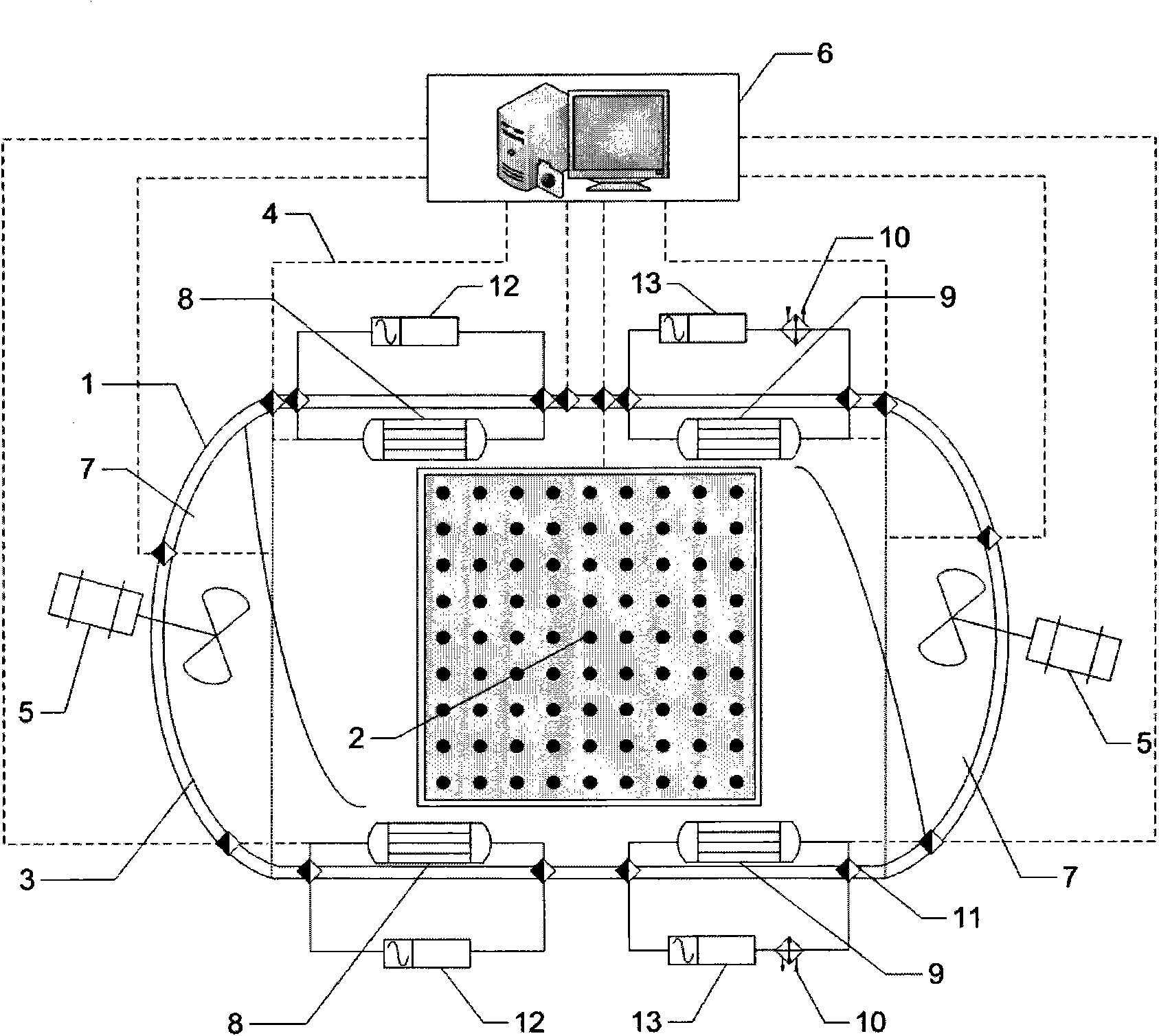
The invention relates to a method and a device for simulating formation temperature in a multi-element thermal fluid injected oil extraction three-dimensional simulation test. A model body is fixed in a hyperbaric chamber; thermocouples are distributed in the hyperbaric chamber to be connected with a computer; two electric heating coils are positioned on upper and lower inner walls of the hyperbaric chamber and are connected with two upper and lower temperature controllers one outside the hyperbaric chamber; and two circulating fluid coils are positioned on the upper and lower inner walls of the hyperbaric chamber and are connected with two upper and lower refrigerating devices with a compressor and two temperature controllers two, which are positioned outside the hyperbaric chamber, respectively to form two upper and lower enclosed circulation loops. Air ducts are arranged in end covers on two sides of the hyperbaric chamber; two magnetic stirrers are positioned on the end covers on two sides of the hyperbaric chamber; and blades of the magnetic stirrers are arranged in the air ducts of the hyperbaric chamber and pass through the end covers of the hyperbaric chamber to be connected with a motor outside the hyperbaric chamber through a motor shaft. The method and the device have the advantages of compact system structure, uniform and stable simulated temperature field, wide range of the simulated temperature, quick temperature rise / reduction process, and low energy consumption.
Description
Technical field: [0001] The invention relates to a simulation device method and application of a high-temperature (350°C) high-pressure (20MPa) three-dimensional simulation test formation temperature for oil recovery by injecting multi-component thermal fluid. Background technique [0002] Multivariate thermal fluid: refers to the medium that can be used for crude oil displacement under reservoir conditions and is heated by the reservoir itself or artificially, including hot water, steam, hot solvent and heated non-condensable gas and other simple substances and their mixtures. [0003] The high-temperature and high-pressure three-dimensional simulation test device for multi-component thermal fluid injection can carry out the research on the technology of improving oil recovery by using various methods such as steam injection, gas injection, and hot solvent injection under the conditions of reservoir pressure 20MPa and temperature 350°C, which can be reproduced to the greates...
Claims
Application Information
Patent Timeline
Application Date:The date an application was filed.
Publication Date:The date a patent or application was officially published.
First Publication Date:The earliest publication date of a patent with the same application number.
Issue Date:Publication date of the patent grant document.
PCT Entry Date:The Entry date of PCT National Phase.
Estimated Expiry Date:The statutory expiry date of a patent right according to the Patent Law, and it is the longest term of protection that the patent right can achieve without the termination of the patent right due to other reasons(Term extension factor has been taken into account ).
Invalid Date:Actual expiry date is based on effective date or publication date of legal transaction data of invalid patent.

