Pressure Control Valve Engine Crankcase Ventilation

A crankcase ventilation and pressure control technology, applied in crankcase ventilation, engine components, machines/engines, etc., can solve problems such as increasing engine pollution

Active Publication Date: 2011-11-30
东风朝阳朝柴动力有限公司
View PDF0 Cites 2 Cited by
  • Summary
  • Abstract
  • Description
  • Claims
  • Application Information

AI Technical Summary

Problems solved by technology

In addition, because the combustible mixture and exhaust gas escape into the crankcase, the pressure in the crankcase will increase, and the oil will seep from the crankshaft oil seal, crankcase gasket, etc., especially at high temperatures, the steam of the oil will increase. air pollution from engines

Method used


Image

  • Pressure Control Valve Engine Crankcase Ventilation
  • Pressure Control Valve Engine Crankcase Ventilation
  • Pressure Control Valve Engine Crankcase Ventilation

Examples


Embodiment Construction

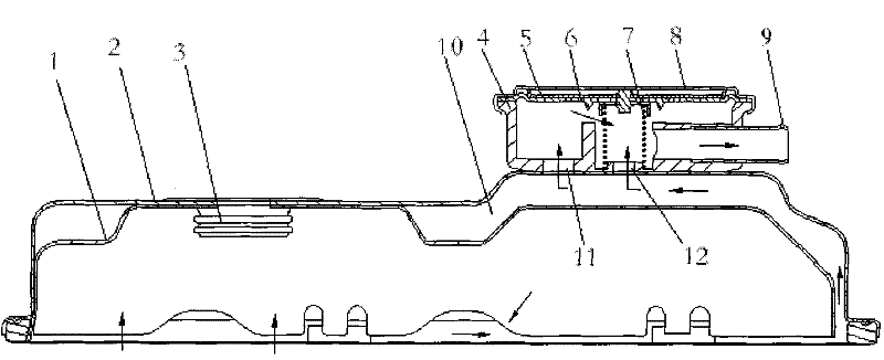
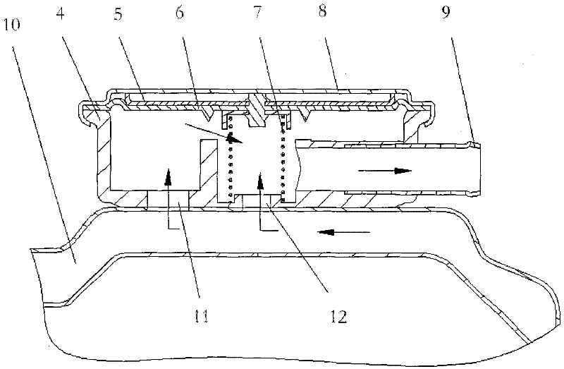
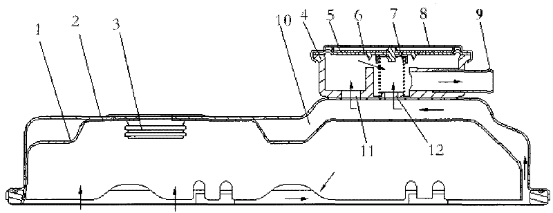
[0008] The structural principles of the present invention will be described in more detail below through embodiments in conjunction with the accompanying drawings. The pressure control valve type engine crankcase ventilation device has a cylinder head cover inner shell 1, a cylinder head cover outer shell 2, an oil filler port 3, a pressure valve seat 4, a support frame 5, a pressure valve body 6, a pressure spring and a spring seat 7, Pressure valve cover 8, outlet pipe 9 etc. A sandwich cylinder head cover 10 can be formed from the cylinder head cover inner shell 1 and the cylinder head cover outer shell 2 . A pressure control valve type ventilation device is composed of a pressure valve seat 4, a support frame 5, a pressure valve body 6, a pressure spring and a spring seat 7, a pressure valve cover 8, and an air outlet pipe 9, and is connected with the cylinder head cover 10 as a whole. The pressure valve seat 4 and the pressure valve body 6 form an inner cavity, and the e...


PUM


Abstract

The invention discloses a device for separating and ventilating oil and gas in an engine crankcase. A sandwich cylinder head cover is formed by the inner shell, and an oil-gas separation and ventilation device is composed of a pressure valve seat, a supporting frame, a pressure valve body, a pressure spring, a pressure valve cover and an air outlet pipe, and is connected with the crankcase as a whole. The pressure valve seat and the pressure valve body form an inner cavity, and the end wall of the inner cavity is provided with an air outlet pipe connected to the engine intake pipe. The pressure valve body is fixed on the pressure valve seat, and the center of the pressure valve body is provided with a pressure spring. The support frame is placed on the pressure valve body, and the pressure valve cover is sealed and fixed on the end surface of the support frame and the pressure valve seat. An oil filling port is arranged on the upper end of the crankcase, and two small holes communicated with the inner shell of the crankcase are opened on the bottom surface of the pressure valve seat. The invention recycles and uses the combustible mixed gas and exhaust gas that have entered the crankcase, which is beneficial to improving the economical efficiency of the engine, reducing the emission pollution of the engine, and ensuring the stability of the engine oil lubrication under various working conditions.

Description

technical field [0001] The invention belongs to engine components, in particular to a device for separating and ventilating oil and gas in the crankcase of the engine. Background technique [0002] During the working process of a diesel engine, there is always a part of the combustible gas mixed with air and diesel oil and the exhaust gas discharged from the cylinder into the crankcase through the piston ring. The physical parameters of the oil change. What's more serious is that the exhaust gas contains water vapor and sulfur dioxide, and the water vapor condenses in the engine oil to form foam, which destroys the oil supply. This phenomenon is especially serious in winter. Sulfur dioxide meets water to form sulfurous acid, and sulfurous acid meets oxygen in the air to form sulfuric acid. The appearance of these acidic substances not only deteriorates the engine oil, but also corrodes the parts. In addition, because the combustible mixture and exhaust gas escape into the ...

Claims


Application Information

Patent Timeline
Patent Type & Authority Patents(China)
IPC IPC(8): F01M13/04
Inventor 李晓刚张宏辉吴广仓陈玉荣
Owner 东风朝阳朝柴动力有限公司
Why Eureka
Try Eureka