Charge pump circuit with low power consumption

A technology of charge pump and low power consumption, which is applied in the direction of conversion equipment without intermediate conversion to AC, which can solve the problem of increase of charge pump charging transient current and transient power consumption, decrease of charge pump charge transfer efficiency, large transient current and transient power consumption to achieve the effect of reducing the peak current

Inactive Publication Date: 2010-10-20
TSINGHUA UNIV
View PDF4 Cites 17 Cited by
  • Summary
  • Abstract
  • Description
  • Claims
  • Application Information

AI Technical Summary

Problems solved by technology

[0004] However, there are two problems in the above-mentioned existing N-stage charge pump circuit: one is that when the clock signal jumps from a low level to a high level, multiple capacitors need to be charged at the same time, so a large transient current and transient power consumption
As the number of stages N increases, the transient current and transient power consumption of the charge pump will increase linearly
Second, as the power supply voltage drops, the charge transfer transistor M 0 ~ M N The offset effect of the charge pump is very serious, which makes the charge transfer efficiency of the charge pump significantly reduced. Therefore, more charge pump stages are required to generate the required voltage, and the area and power consumption of the charge pump will increase significantly.

Method used


Image

  • Charge pump circuit with low power consumption
  • Charge pump circuit with low power consumption
  • Charge pump circuit with low power consumption

Examples


Embodiment Construction

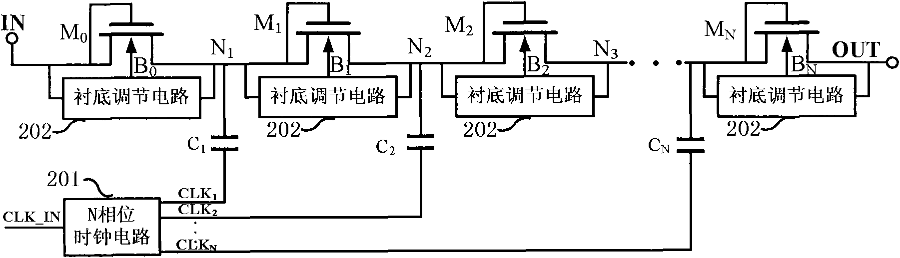
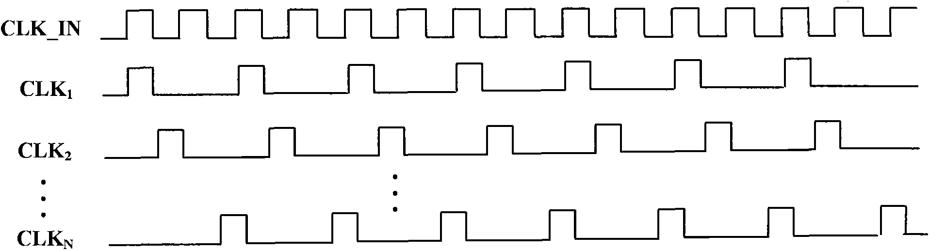
[0030] figure 2 Shown is a schematic structural diagram of a charge pump circuit according to an embodiment of the present invention. Such as figure 2 As shown, the charge pump circuit consists of NMOS transistors M 0 ~ M N , substrate adjustment circuit 202, multi-phase clock circuit 201 and capacitive element C 1 ~C N . where the NMOS transistor M 0 ~ M N It is connected in series between the input terminal IN and the output terminal OUT of the circuit. The gate and drain of the NMOS transistor are connected together to form a diode connection mode of the MOS transistor, which has the characteristic of unidirectional conduction. During the working process of the charge pump, it is through the unidirectional conduction characteristic of the NMOS transistor that the charge is continuously transferred from the front end to the output terminal OUT. The substrate potential of each NMOS transistor is provided by the substrate adjustment circuit 202, and the input termin...


PUM


Abstract

The invention relates to a charge pump circuit with low power consumption. The charge pump circuit comprises a multiphase clock generation circuit, a charge transmission transistor, a substrate adjustment circuit of the charge transmission transistor and a capacitor element, wherein one end of the capacitor element is connected to a serial connection joint of the charge transmission transistor, and the other end is connected to clock signals generated by the multiphase clock circuit; the plurality of clock signals output by the multiphase clock generation circuit have different phases, and each clock signal is connected to the corresponding capacitor element so that the charge pump only charges one capacitor when working at different moments. The invention can effectively avoid larger transient current and transient power consumption caused by charging the plurality of capacitors in the traditional charge pump circuit at the same time, and thereby the dynamic power consumption and power peak current are reduced when the charge pump works.

Description

technical field [0001] The invention belongs to the technical field of integrated circuit design, and relates to a charge pump circuit (Charge Pump Circuit) generating high voltage from low voltage, in particular to a charge pump circuit with low power consumption. Background technique [0002] In a single-supply system, the charge-pump circuit can provide a voltage higher than the supply potential. Charge pump circuits are widely used in non-volatile semiconductor memory, liquid crystal driver IC, DC-DC conversion and other fields. For example, in non-volatile memory, the charge pump circuit provides a high voltage much higher than the power supply voltage to realize storage Unit programming and erasing operations. [0003] Charge pump circuits exploit the storage properties of charge in capacitive elements to generate higher voltages. For a capacitive element, if the capacitor is first charged to a predetermined voltage, and then the polarity of the potential at one end ...

Claims


Application Information

Patent Timeline
Patent Type & Authority Applications(China)
IPC IPC(8): H02M3/07
Inventor 王雪强潘立阳伍冬周润德
Owner TSINGHUA UNIV
Why Eureka
Try Eureka