
Laser vibration deposition device and laser vibration deposition method under condition of integral heat insulation

A technology of cladding and conditioning, applied in the field of laser surface modification, to achieve the effect of improving performance

Inactive Publication Date: 2010-10-27
SOUTH CHINA UNIV OF TECH
View PDF3 Cites 14 Cited by
  • Summary
  • Abstract
  • Description
  • Claims
  • Application Information

AI Technical Summary

Problems solved by technology

[0004] The purpose of the present invention is to reduce or eliminate the problems of pores and cracks in the cladding layer in the existing laser cladding technology, and to provide a laser vibration cladding device and method under the condition of overall heat preservation

Method used


Image

  • Laser vibration deposition device and laser vibration deposition method under condition of integral heat insulation
  • Laser vibration deposition device and laser vibration deposition method under condition of integral heat insulation

Examples


Embodiment 1

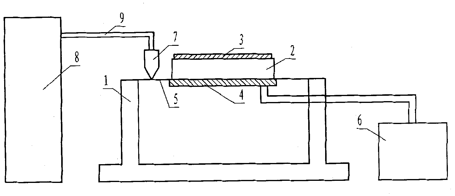
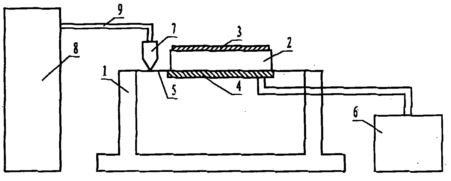
[0027] The method for applying the above-mentioned device to laser vibration cladding under the condition of overall heat preservation comprises the following steps:

[0028] Step 1. Mix aluminum powder with a particle size of 200 mesh and rosin alcohol solution. The rosin alcohol solution is 5g of rosin for every 50ml of alcohol, and 3ml of rosin alcohol solution is added for every 10g of aluminum powder; spread the mixture evenly on the surface of the AZ31B magnesium alloy plate and Drying; smear about 2mm thick to form the powder to be welded 3. The size of the AZ31B magnesium alloy plate can be selected as follows: length 150mm, width 70mm, thickness 10mm.

[0029] Step 2, clamping the AZ31B magnesium alloy plate coated with the powder 3 to be deposited on the vibrating workbench;

[0030] Step 3: Arrange a temperature-controlled heating belt 4 under the AZ31B magnesium alloy plate, and use a temperature controller 6 to keep the entire workpiece within a temperature range...

Embodiment 2

[0037] Step 1. Mix nickel powder with a particle size of 100 mesh and rosin alcohol solution (50ml alcohol plus 5g rosin, add 1ml rosin alcohol solution for every 10g nickel powder; apply the mixture evenly on the surface of No. 45 steel plate and dry it; smear about 2mm Thickness; the size of No. 45 steel plate is 150mm long, 70mm wide and 10mm thick.

[0038] Step 2, clamping the No. 45 steel plate coated with the mixture of nickel powder and rosin alcohol solution on the vibrating workbench;

[0039] Step 3. Arrange a temperature-controlled heating belt under the No. 45 steel plate, and make the entire workpiece within the range of 300°C ± 20°C through the temperature control system;

[0040] Step 4. Start the vibration generator to drive the workpiece to vibrate through the vibration head, and the vibration frequency is 50Hz;

[0041] Step 5. Use a 5000W CO2 laser to scan at a speed of 1200mm / min, under argon protection, with a lap rate of 50%, and perform laser cladding ...

Embodiment 3

[0045]Step 1. Mix copper powder with a particle size of 200 mesh and rosin alcohol solution (50ml alcohol plus 5g rosin), wherein 1ml rosin alcohol solution is added for every 5g copper powder; apply the mixture evenly on the surface of No. 45 steel plate and dry it; About 2mm thick; the size of the No. 45 steel plate is 150mm long, 70mm wide and 10mm thick.

[0046] Step 2, clamping the No. 45 steel plate coated with the mixture of copper powder and rosin alcohol solution on the vibration table;

[0047] Step 3. Arrange a temperature-controlled heating belt under the No. 45 steel plate, and make the entire workpiece within the range of 400°C ± 20°C through the temperature control system;

[0048] Step 4. Start the vibration generator to drive the workpiece to vibrate through the vibration head, and the vibration frequency is 50Hz;

[0049] Step 5. Use 5000W CO 2 The laser scans at a speed of 900mm / min, protected by argon, with a lap rate of 40%, and performs laser cladding ...


PUM

PropertyMeasurementUnit
particle sizeaaaaaaaaaa

Abstract

The invention discloses a laser vibration deposition device and a laser vibration deposition method under the condition of integral heat insulation. A spring piece is arranged on a vibration table of the laser vibration deposition device; a temperature control heater band is fixed below the spring piece and is connected with a temperature controller; a vibration generator is connected with the spring piece through a vibration arm and a vibration head; the spring piece is in a flat shape; and a to-be-deposited metal plate is fixed on the spring piece. The method comprises the following steps that: required powder is coated on the to-be-deposited metal plate, and the to-be-deposited metal plate is arranged on a vibration workbench; the temperature control heater band is arranged below a to-be-deposited workpiece, so that the integral workpiece is at the temperature of between 80 and 420 DEG C; the workpiece is driven to vibrate by starting the vibration device in the vibration frequency of between 20 and 200 Hz; and the scanning is performed by using a CO2 laser to perform laser deposition under the condition of vibration. The laser vibration deposition device and the laser vibration deposition method inhibit air holes and cracks from being formed in the conventional laser deposition technology effectively, and can improve deposition layers and interface tissue and improve the performance of wear resistance, corrosion resistance, heat-temperature resistance and the like of the deposition layers.

Description

technical field [0001] The invention relates to a laser surface modification method. technical background [0002] Modern industrial applications have higher and higher requirements for the comprehensive performance of metal materials, and at the same time, production costs must be minimized. Laser cladding can generate a surface layer with the desired composition and properties on the surface of cheap alloys, thereby improving the surface properties of materials such as hardness, wear resistance, corrosion resistance, oxidation resistance, heat resistance, etc., making cheap alloys more widely available applications, reducing manufacturing costs. Laser cladding is to apply powder with special properties (such as wear resistance, corrosion resistance, etc.) Coating material with specific properties in thin layers. [0003] However, the cladding layer prepared by the current laser cladding process generally has the problems of pores and cracks. The existence of pores makes...

Claims


Application Information

Patent Timeline
Patent Type & Authority Applications(China)
IPC IPC(8): B22F7/04B22F3/105
Inventor 张超平李勇陈春燕何恒飞
Owner SOUTH CHINA UNIV OF TECH
Learn More