Loading device of hydraulic motor test board

A technology of loading device and hydraulic motor, which is applied in the direction of fluid pressure actuation device, fluid pressure actuation system test, mechanical equipment, etc. It can solve the problems of high maintenance cost, many components, poor practicability, etc., and achieve easy maintenance , less investment, and a wide range of testing effects

Active Publication Date: 2010-10-27
宁波恒通诺达液压股份有限公司
View PDF3 Cites 33 Cited by
  • Summary
  • Abstract
  • Description
  • Claims
  • Application Information

AI Technical Summary

Problems solved by technology

[0003] The current manufacturer uses a magnetic powder brake as the output load of the test motor in the test, and the magnetic powder brake is based on the electromagnetic principle and uses magnetic powder to transmit torque. The magnetic powder brake is connected to the hydraulic motor of the test piece. It has many components, large volume and energy consumption High cost, high cost, difficult maintenance, and it has a linear relationship between the excitation current and the transmission torque. It needs a steady current power supply produced by a professional manufacturer as its special power supply. It is prone to jamming during the work process. High-power The magnetic powder brake also needs water cooling, so using the magnetic powder brake as the output load of the test motor has high cost, high maintenance cost, and poor practicability

Method used


Image

  • Loading device of hydraulic motor test board
  • Loading device of hydraulic motor test board

Examples


Embodiment Construction

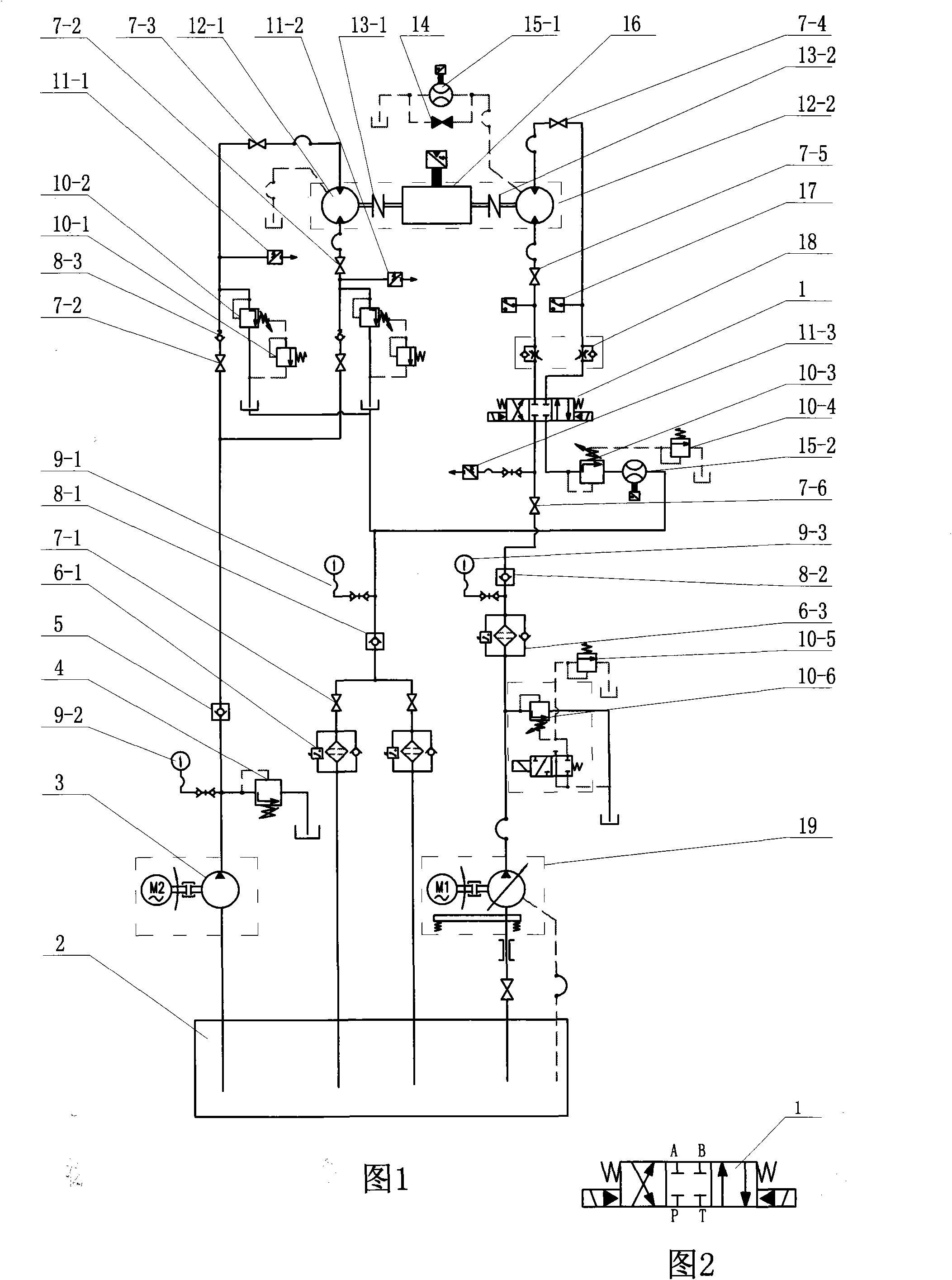
[0015] Embodiments of the present invention will be further described below in conjunction with the accompanying drawings.

[0016] The electro-hydraulic reversing valve is a three-position four-way reversing valve 1.

[0017] The high-pressure pump is a high-pressure variable plunger pump 19, and the low-pressure pump is a low-pressure gear pump 3

[0018] The oil suction end of the high-pressure variable oil pump 19 is connected with the oil tank 2, and the other end of the oil outlet is connected with the pilot overflow valve 10-5, the remote overflow valve C 10-6, and the high-pressure filter 6-3, and the oil outlet of the high-pressure filter is connected with the The oil inlet of the oil inlet check valve 8-2 is connected with the pressure gauge A 9-3

[0019] The outlet of the oil inlet check valve 8-2 is connected to the P port of the three-position four-way reversing valve 1 through the main high-pressure ball valve 7-6, and the P port is also connected to the pressu...


PUM


Abstract

The invention relates to a loading device of a hydraulic motor test board, which is characterized in that a high-pressure oil pump which is connected with an oil tank is connected with an electro-hydraulic reversing valve, a bi-direction retaining throttling valve and a test motor oil inlet through a high-pressure filter and an oil inlet retaining valve, a test motor oil outlet forms a test loop with an oil return retaining valve and an oil return filter oil return box after being connected with a remote counterbalance overflow valve, a flow-rate sensor, through the bi-direction retaining throttling valve and an electro-hydraulic reversing valve oil outlet. A loader is formed by joining a loading motor and a testing motor respectively with a rotation speed torque instrument through a coupling joint, at the same time, a low-pressure pump which is connected with the oil tank enters two ends of the loading motor through two retaining valves, the testing motor rotates to drive the loading motor to rotate, the oil outlet retaining valve is automatically closed, and the outlet oil forms a loading circuit through the counterbalance overflow valve, the remote overflow valve, the oil return retaining valve and the oil return filter oil return box. The loading motor is used for substituting an original magnetic powder loader, so the size is greatly reduced, the energy consumption is reduced, the remote control adjustment is convenient for test personnel to work, the loading force is large, torque of 60000 N.m can be tested, the testing range is wide, and the practicability is strong.

Description

technical field [0001] The invention relates to an important part of a hydraulic motor test bench, in particular to a loading device of the hydraulic motor test bench used for testing the output load of the motor. Background technique [0002] Before the hydraulic motor leaves the factory, in order to ensure the product quality, each hydraulic motor must be tested for performance, such as pressure, flow, torque, speed, performance, etc., and the qualified product can only be shipped if it meets the design requirements. [0003] The current manufacturer uses a magnetic powder brake as the output load of the test motor in the test, and the magnetic powder brake is based on the electromagnetic principle and uses magnetic powder to transmit torque. The magnetic powder brake is connected to the hydraulic motor of the test piece. It has many components, large volume and energy consumption High cost, high cost, difficult maintenance, and it has a linear relationship between the exc...

Claims


Application Information

Patent Timeline
Patent Type & Authority Applications(China)
IPC IPC(8): F15B19/00
Inventor 徐文利
Owner 宁波恒通诺达液压股份有限公司
Why Eureka
Try Eureka