Separate low pressure coal economizer of elliptical fin heat pipe

A low-pressure economizer and elliptical fin technology, which is applied in the field of boiler waste heat recovery and energy-saving equipment, can solve the problems of boiler low-pressure economizer tube row wear, large heat exchanger volume, and high resistance, so as to improve cycle heat efficiency and heat transfer Good performance and low flow resistance

Inactive Publication Date: 2010-11-10
HEILONGJIANG ELECTRIC POWER RES INST
View PDF8 Cites 9 Cited by
  • Summary
  • Abstract
  • Description
  • Claims
  • Application Information

AI Technical Summary

Problems solved by technology

[0003] The purpose of the present invention is to solve the problem of large heat exchanger volume and high resistance in the existing boiler low-pressure economizer, resulting in high investment, and serious wear and tear of the tube row on the boiler low-pressure economizer, and then provides a separation Type elliptical fin heat pipe low pressure economizer

Method used


Image

  • Separate low pressure coal economizer of elliptical fin heat pipe
  • Separate low pressure coal economizer of elliptical fin heat pipe

Examples


specific Embodiment approach 1

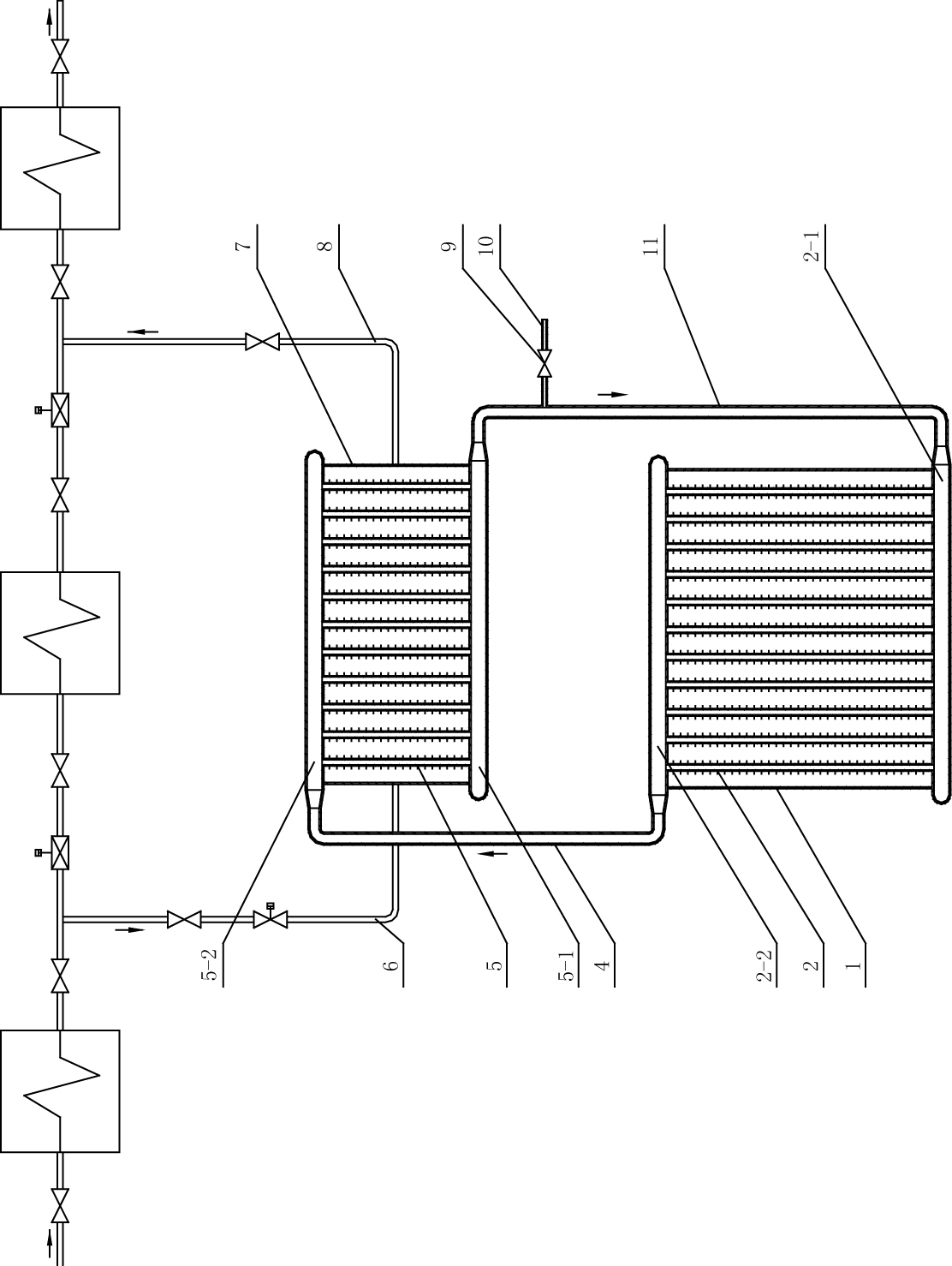
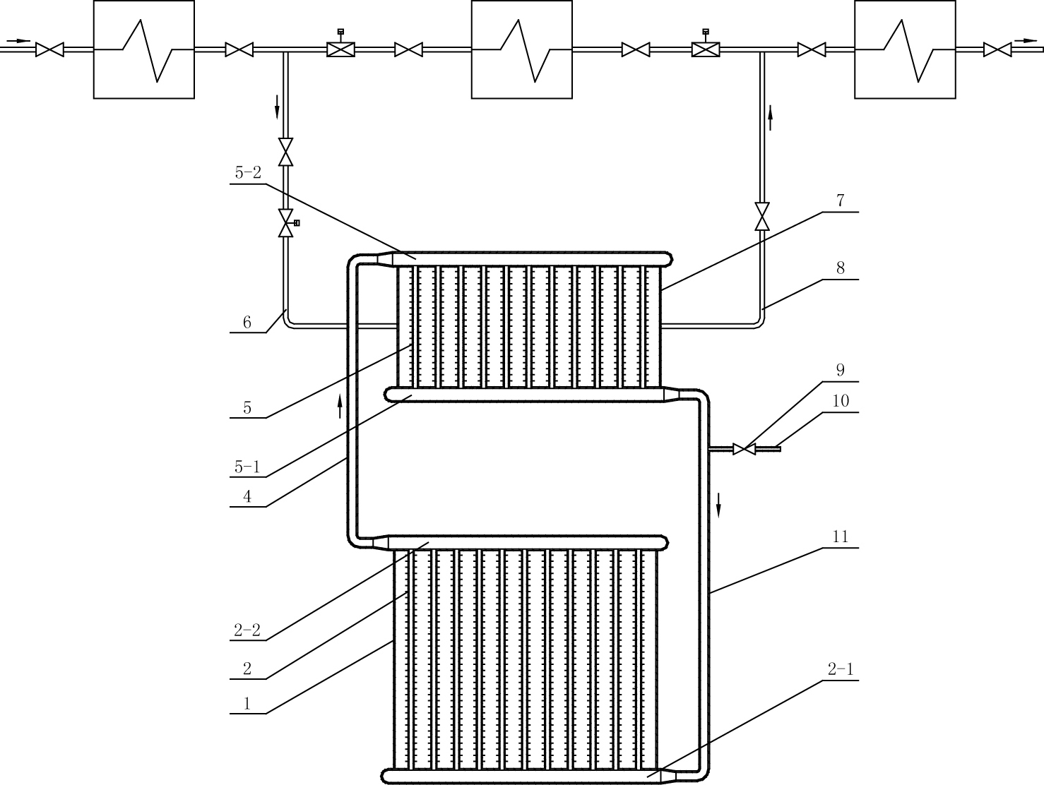
[0008] Specific implementation mode 1: Combination figure 1 The low-pressure economizer of the separated elliptical fin heat pipe of this embodiment includes an elliptical fin heat pipe evaporation section tube panel 2, an elliptical fin heat pipe condensing section tube panel 5, a steam air duct 4, and a return pipe 11. The tube panel 2 of the evaporation section of the finned heat pipe is composed of a number of parallel elliptical fin heat pipes, a condensate inlet header 2-1 and a steam outlet header 2-2. Each of the elliptical finned heat pipe evaporation section tube panels 2 The two ends of the elliptical fin heat pipe are respectively communicated with the condensate inlet header 2-1 and the steam outlet header 2-2. The elliptical fin heat pipe condensation section tube panel 5 is composed of a plurality of parallel elliptical fin heat pipes and condensation The water outlet header 5-1 and the steam inlet header 5-2 are composed. The two ends of each oval fin tube in th...

specific Embodiment approach 2

[0009] Specific implementation manner two: combination figure 1 The low-pressure economizer of the separated elliptical fin heat pipe of this embodiment will be described. It also includes an exhaust pipe 10 and an exhaust valve 9. The exhaust valve 9 is arranged on the exhaust pipe 10, and the exhaust pipe 10 is located on the water pipe. 11 is above and communicates with the water pipe 11. The non-condensable gas in the condensation section can be released through the exhaust pipe 10 to ensure the heat transfer performance of the separated heat pipe. The other components and connection relationships of this embodiment are the same as those of the first embodiment.

specific Embodiment approach 3

[0010] Specific embodiment 3: In the separated elliptical fin heat pipe low-pressure economizer of this embodiment, the elliptical fin heat pipe is a copper tube or a steel pipe. The other components and connection relationships of this embodiment are the same as those of the first or second embodiment.


PUM


Abstract

The invention relates to a separate low pressure coal economizer of an elliptical fin heat pipe, relating to boiler waste heat recovery energy-saving equipment, in particular to a separate low pressure coal economizer of an elliptical fin heat pipe. The invention solves the problems of high investment and severe abrasion of banks of pipes caused by large volume and high resistance of a heat exchanger of the traditional boiler low pressure coal economizer. In the invention, both ends of a plurality of elliptical fin heat pipes arranged in parallel in a pipe panel of an evaporation section of the elliptical fin heat pipes are respectively communicated with a corresponding condensation water inlet header and a steam outlet header; both ends of a plurality of elliptical fin heat pipes arranged in parallel in a pipe panel of a condensation section of the elliptical fin heat pipes are respectively communicated with a corresponding condensation water outlet header and a corresponding steam inlet header; the steam outlet header of the pipe panel of the evaporation section is communicated with the steam inlet header of the pipe panel of the condensation section through a steam gas guide tube; and the condensation water outlet header of the pipe panel of the condensation section is communicated with the condensation water inlet header of the pipe panel of the evaporation section through a water return pipe. The invention is particularly suitable for the utilization of the waste heat of the discharge smoke of an electric plant boiler.

Description

Technical field [0001] The invention relates to a boiler waste heat recovery energy-saving equipment, in particular to a separated elliptical fin heat pipe low-pressure economizer. Background technique [0002] Boiler exhaust gas is a potential waste heat source. How to reduce exhaust gas waste heat and reduce heat loss caused by exhaust gas has become one of the main issues studied by boiler technicians. The low-pressure economizer is installed at the end of the boiler, and its water side is connected to the low-pressure part of the steam turbine regenerative system. The condensed water absorbs the heat of exhaust gas in the low-pressure economizer and reduces the exhaust gas temperature, but it is heated by itself. Returning to the low-pressure heater system again, under the condition of constant fuel consumption, more electric power can be obtained, which improves the economy of the device. It is an integral part of the steam turbine thermal system. In the existing low-pressu...

Claims


Application Information

Patent Timeline
IPC IPC(8): F22D1/00F28D15/02F28F1/02F28F1/12
Inventor 鞠胤红杨利民
Owner HEILONGJIANG ELECTRIC POWER RES INST
Why Eureka
Try Eureka