Monitoring system and method of remote temperature image of substation

A temperature image and monitoring system technology, applied in the field of substation remote image monitoring technology, can solve personal safety and health threats, reduce work efficiency, resource waste and other problems, to avoid the impact of data transmission, avoid electromagnetic impact, and reduce work volume effect

Active Publication Date: 2010-11-10
GUANGZHOU KEII ELECTRO OPTICS TECH
View PDF3 Cites 17 Cited by
  • Summary
  • Abstract
  • Description
  • Claims
  • Application Information

AI Technical Summary

Problems solved by technology

One method is manual detection, which has the following disadvantages: First, the staff needs to use a handheld thermal imaging camera to take pictures of the substation equipment item by item, and then perform subsequent analysis and processing, which has a long working cycle and low efficiency. The real-time information cannot be realized; secondly, this detection method obtains one or several heat maps, which are not continuous in time, and subsequent processing requires staff to draw results based on experience, and the reliability is low; thirdly, The staff have to work in a strong electromagnetic environment, and their personal safety and health are threatened
Another way is to densely arrange high-resolution infrared thermal imaging monitoring equipment in the substation. The hardware cost of this method is high, and most substations cannot afford it. Moreover, for remote monitoring personnel, too many front-end monitoring equipment will also cause problems. Increase the workload of monitoring work, cause waste of resources and reduce work efficiency

Method used


Image

  • Monitoring system and method of remote temperature image of substation
  • Monitoring system and method of remote temperature image of substation
  • Monitoring system and method of remote temperature image of substation

Examples


Embodiment 1

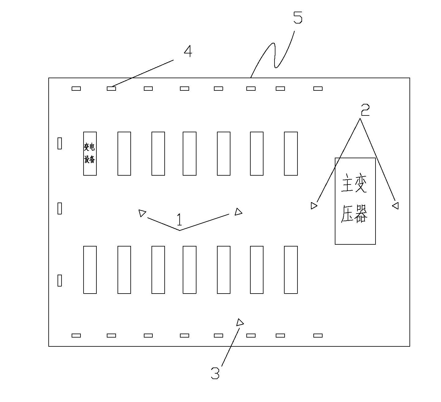
[0028] Such as figure 1 and figure 2 As shown, there are two high-resolution panoramic monitoring infrared thermal imaging cameras 1 at the central position in the substation 5. The panoramic monitoring infrared thermal imaging cameras are used to monitor all general equipment in the substation except the main transformer. The panoramic monitoring infrared thermal imaging cameras The camera is equipped with a pan-tilt that can rotate freely within a 360-degree viewing angle; the panoramic monitoring infrared thermal imager has a long detection distance and a short monitoring time, so it is impossible to judge the cause and level of the fault. In order to overcome this defect, when the panoramic monitoring infrared thermal imager When the thermal imager detects a fault, use a medium-resolution mobile monitoring infrared thermal imager 3 to monitor the fault location for a cycle; two low-resolution fixed-point monitoring infrared thermal imaging cameras are installed on the fro...

Embodiment 2

[0031] refer to figure 2 As shown, on the basis of embodiment 1, the method for remote temperature image monitoring of the substation comprises the following steps: a, two high-resolution panorama monitoring infrared thermal imaging cameras 1 are arranged in the substation 5 to conduct panorama of the substation Monitoring, so that the monitoring range of each panoramic monitoring thermal imaging camera is the largest and the monitoring range overlap is the smallest, wherein any device in the substation is covered by the monitoring range of at least one panoramic monitoring thermal imaging camera; b. High-rate fixed-point monitoring thermal imager 2 is set on the front and rear sides of the main transformer to monitor the main transformer; c. When an abnormal device is found in step a, use a mobile monitoring thermal imager 3 with a medium resolution to check the abnormal device periodic monitoring.

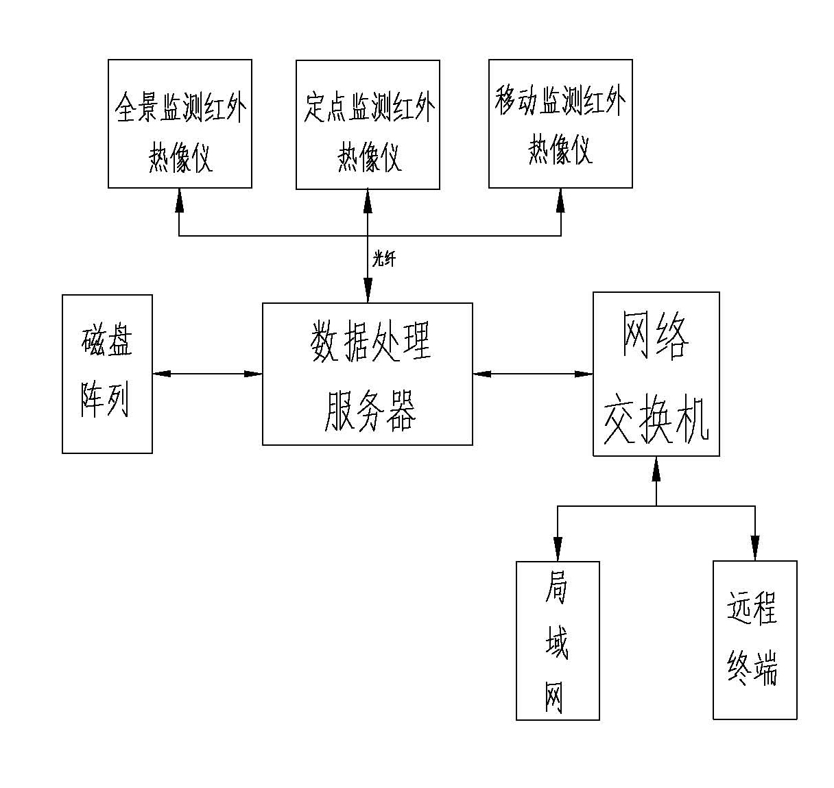
[0032] The information collected in the above three steps is transmitted t...

Embodiment 3

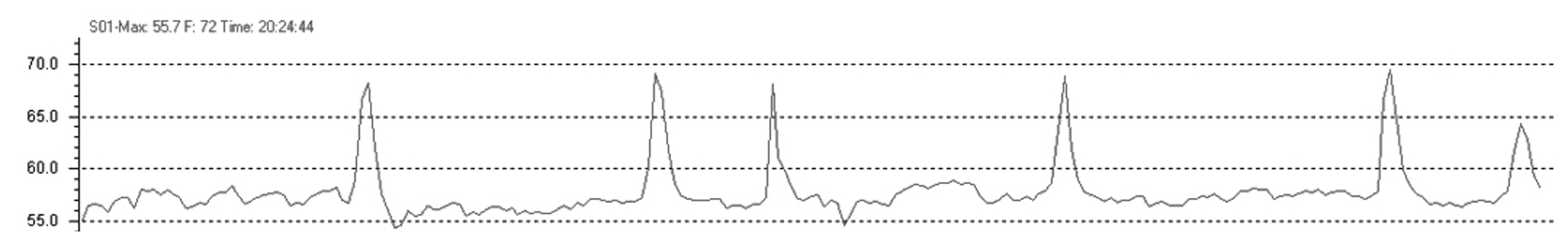
[0039] see image 3 . image 3 It is the temperature analysis curve of this system for the fault detection of the low-voltage side of the 220Kv main transformer. The detection time is at midnight, where C03 is the temperature curve of B phase, and C01 is the temperature curve of A phase. From the temperature analysis curve, it is known that when the equipment is at midnight, the power consumption decreases, and the temperature of phase B (C03) decreases, but the temperature of phase A (C01) does not decrease with the decrease of load, which shows that phase A is not a simple Poor contact, but a thermal defect caused by voltage and current loads. The above defects cannot be determined by general hand-held testing equipment.


PUM


Abstract

The invention discloses monitoring system and method of a remote temperature image of a substation. In the system, a panoramic monitoring thermal infrared imager, a fixed point monitoring thermal infrared imager and a movable monitoring thermal infrared imager are connected with a data processing server through a network interface; and a monitoring terminal is connected with the data processor through a network switch. The panoramic monitoring thermal infrared imager and the fixed point monitoring thermal infrared imager in the system can be used for carrying out fixed point monitoring by matching high resolution with low resolution on the substation; and the movable monitoring thermal infrared imager with intermediate resolution is used for further monitoring fault equipment so as to determine faults. The remote temperature image monitoring is carried out on the substation by using a method of combining the matching of the high resolution and the low resolution, fixed movement and network communication. The invention has the advantages of low cost of the input and the use of monitoring equipment, complete and accurate monitoring, high efficiency and remote and unmanned duty.

Description

technical field [0001] The invention relates to a remote monitoring technology of a substation, in particular to a remote image monitoring technology of a substation using an infrared thermal imager. [0002] Background technique [0003] With the gradual deepening of power system reform and the demand for smart grid development, the power system is facing unprecedented competitive pressure. In recent years, more and more advanced technologies have been applied to the power industry, which has brought the comprehensive automation management of substations in the power industry to a new level. , 110kV, and 220kV substations will be unattended gradually when the conditions are ripe, and new substations should be designed in an unattended manner. However, at present, the power industry generally adopts video environment image monitoring, and there is a problem of insulation detection of substation equipment, and usually requires a special person to regularly inspect the subst...

Claims


Application Information

Patent Timeline
Patent Type & Authority Applications(China)
IPC IPC(8): H02J13/00
CPCY04S40/126Y02E60/7853Y02E60/00
Inventor 吴晓松
Owner GUANGZHOU KEII ELECTRO OPTICS TECH
Why Eureka
Try Eureka