Heat pipe cutter and method for improving radiation of cutting tool by using heat pipe
A heat pipe and tool technology, which is applied to the accessories of tool holders, tools for lathes, turning equipment, etc., can solve the problems of environmental pollution and high cost, and achieves lower temperature of the tool head, low cost, and low cost of making heat pipe tools. Effect
- Summary
- Abstract
- Description
- Claims
- Application Information
AI Technical Summary
Problems solved by technology
Method used
Image

Examples
Embodiment 1
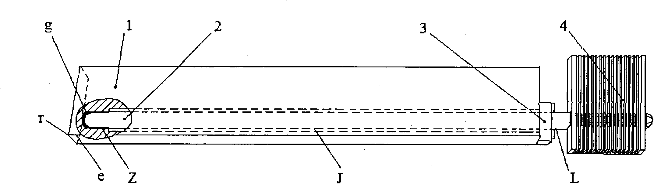
[0031] Such as figure 1 As shown, the built-in heat pipe tool using heat pipes to improve heat dissipation during cutting includes an integral cutter body 1 , heat pipes 2 , support clips 3 and heat sinks 4 . The heat pipe 2 is composed of a metal thin-walled tube shell, a capillary liquid-absorbing core on the inner wall of the tube shell, and a working medium that transfers heat energy, forming a high-vacuum closed system; along the axial direction of the heat pipe, it can be divided into successively connected evaporation section Z, adiabatic section J and Condensation section L; an inner hole is provided in the cutter body 1 for placing the heat pipe 2, the inner hole extends from the tail end to the rear end of the main blade e and the tip r inside the cutter head, and the specific distance from the main blade e and the tip r It needs to be determined according to the material of the tool and the cutting load. Under the premise of ensuring that the tool head has the stren...
Embodiment 2
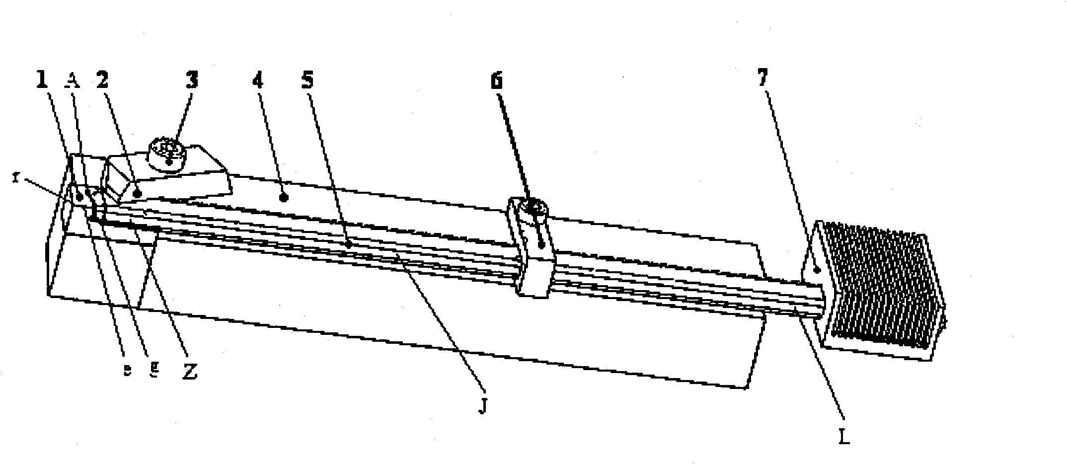
[0034] Such as figure 2 As shown, the groove-embedded heat pipe tool that uses heat pipes to improve heat dissipation during cutting includes a blade 1 , a clamping lever 2 , a set screw 3 , a handle 4 , a heat pipe 5 , a fixed card 6 and a heat sink 7 . The heat pipe 5 is composed of a metal thin-walled tube shell, a capillary liquid-absorbing wick on the inner wall of the tube shell, and a working fluid that transfers heat energy, forming a high-vacuum closed system; along the axial direction of the heat pipe, it can be divided into successively connected evaporation section Z, adiabatic section J and Condensation section L; the rake face A of the blade 1 and the handle 4 are provided with open slots connected to each other, and the open slots extend from the blade 1 to the end of the handle 4 for embedding the heat pipe 5; the front end of the open slot is located on the main blade e and the rear part of the tool nose r, the specific distance can be determined according to...
Embodiment 3
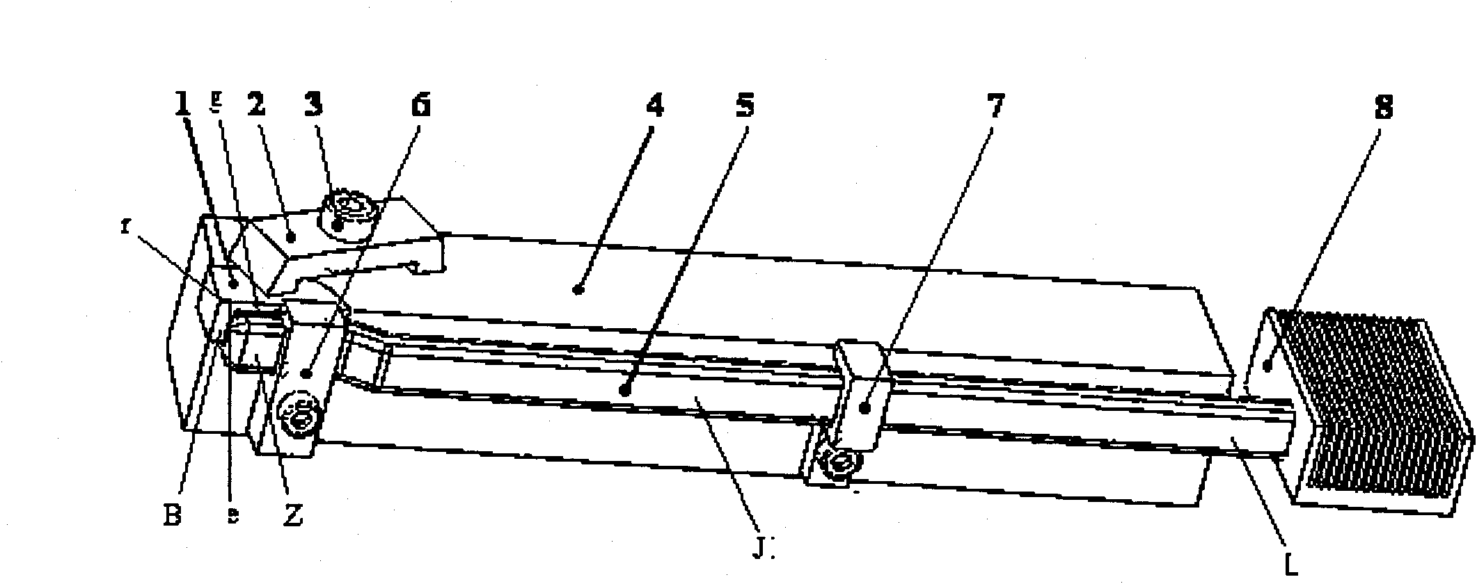
[0037] Such as image 3 As shown, the side-clamp heat pipe tool using heat pipe to improve cutting heat dissipation includes blade 1, clamping lever 2, set screw 3, tool handle 4, heat pipe 5, first fixing card 6, second fixing card 7, heat sink 8. The heat pipe 5 is composed of a metal thin-walled tube shell, a capillary liquid-absorbing wick on the inner wall of the tube shell, and a working fluid that transfers heat energy, forming a high-vacuum closed system; along the axial direction of the heat pipe, it can be divided into successively connected evaporation section Z, adiabatic section J and Condensation section L; the blade 1 is fixed on the blade holder at the front end of the handle 4 by the clamping lever 2 and the set screw 3, the clamping lever 2 and the set screw 3 are the clamping lever and the set screw of the common machining tool The heat pipe 5 is fixed on the flank B of the blade 1 and the side with the handle 4, wherein the contact interface between the ev...
PUM
 Abstract
Description
Claims
Application Information