Intrinsic safety photoacoustic spectrum gas monitoring system based on optical acoustic sensor

A technology of acoustic wave sensor and photoacoustic spectroscopy, which is applied in the field of detection and gas monitoring, can solve problems such as damage, performance impact, and function loss, and achieve the effect of high monitoring sensitivity and fast response speed

Inactive Publication Date: 2012-07-04
SHANDONG ACAD OF SCI INST OF AUTOMATION
View PDF6 Cites 0 Cited by
  • Summary
  • Abstract
  • Description
  • Claims
  • Application Information

AI Technical Summary

Problems solved by technology

In the above patents using the photoacoustic method to detect gas concentration, the light source and on-site data processing circuit used require on-site power supply, which cannot be used in special environments, such as gas environments, and the microphones used are traditional microphones. Traditional microphones include capacitors, electrets and dynamic microphones, which rely on electronic circuits containing capacitors or coils, especially in the first two invention patents (patent publication number: CN 101487818A), CN 101498690A) Due to the strong electromagnetic interference of transformers in the application environment, if no additional anti-electromagnetic interference design is carried out, the external strong electromagnetic field environment will affect the performance of these devices, or even cause their functions to be lost. In the worst case, they will be destroyed. The same is true in radioactive environments this problem

Method used


Image

  • Intrinsic safety photoacoustic spectrum gas monitoring system based on optical acoustic sensor
  • Intrinsic safety photoacoustic spectrum gas monitoring system based on optical acoustic sensor

Examples


Embodiment Construction

[0020] The present invention is described in detail below in conjunction with accompanying drawing and embodiment, and present implementation example has provided detailed embodiment and concrete operation step and is implemented under the premise of technical solution of the present invention, but the scope of protection of the present invention is not limited to Examples described below.

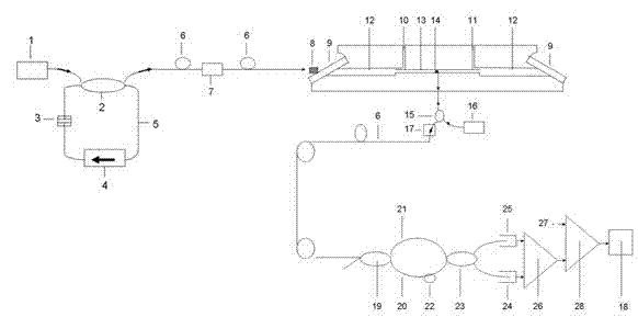
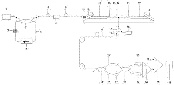
[0021] like figure 1 As shown, the implementation example includes a light source device, the laser generated by the device is connected to the photoacoustic cell device through the optical fiber 6 through the fiber collimator 8, and the incident direction of the laser is collimated with the axis of the photoacoustic cell device; the optical acoustic wave sensor and The photoacoustic cell device is connected, and the photoacoustic cell device communicates with the gas to be measured; wherein the phase-shifted erbium-doped grating optical fiber 14 of the 1 / 4 wavelength in the optical acoust...


PUM


Abstract

The invention relates to an intrinsic safety opto-acoustic spectrum gas monitoring system based on an optical acoustic sensor. The Intrinsic safety opto-acoustic spectrum gas monitoring system comprises a light source device which is connected with a photoacoustic cell device through optical fibers and an optical fiber collimator, and the incident direction of laser emitted from the light source is collinearly aligned with the axle center of the photoacoustic cell device; and phase-shifting erbium-doped grating optical fiber with the 1 / 4 wavelength of the optical acoustic sensor is annularly paved on the inner wall of the photoacoustic cell device, the photoacoustic cell device is communicated with a gas to be tested, and the grating optical fiber is connected with a demodulation device and a data acquisition device. The invention has the advantages of high detection sensitivity, fast response speed, and the like and can realize fast, accurate and long-term on-line monitoring of tracetoxic and harmful gases or other specific gases, in particular to accurate measurement and analysis of gases under some special detection environments, such as the strong electromagnetic environment,the radioactive environment, the environment in a gas-production coal mine which is not allowed to use a power supply device on site, and the like.

Description

technical field [0001] The invention belongs to the field of gas monitoring and detection, and specifically relates to a high-sensitivity on-line intrinsically safe photoacoustic spectrum gas monitoring system based on an optical acoustic wave sensor for monitoring gas content in a special environment (strong electromagnetic, radioactive, and no electricity). Background technique [0002] The photoacoustic effect is based on the effect that the substance absorbs the modulated light and excites the sound wave through non-radiative relaxation and heat release. Due to the high sensitivity of the photoacoustic spectroscopy and the wide detection range, especially not limited by the shape of the sample, it is suitable for solids and liquids. , gas, powder, film, and even biological samples can be directly detected, and thus widely used in many fields such as physics, chemistry, biology, environment, materials, medicine, etc., and has become an important method and means in analys...

Claims


Application Information

Patent Timeline
Patent Type & Authority Patents(China)
IPC IPC(8): G01N21/17G01N21/39
Inventor 刘祥志成巍王知学刘晓建
Owner SHANDONG ACAD OF SCI INST OF AUTOMATION
Why Eureka
Try Eureka