
Composite battery, preparation method and application thereof

A composite battery and battery technology, applied in secondary batteries, nickel batteries, lead-acid batteries, etc., can solve the problems of battery life less than one year, battery life shortening, high price battery consistency, etc., to achieve weight reduction, The effect of prolonging the service life and reducing the volume

Inactive Publication Date: 2010-11-17
韩福忠
View PDF7 Cites 42 Cited by
  • Summary
  • Abstract
  • Description
  • Claims
  • Application Information

AI Technical Summary

Problems solved by technology

However, the lead-acid battery is not perfect. It has low specific energy density, difficult to start at minus 20 degrees, and heavy weight. It requires the battery to release a large current of 300-800A at the moment of ignition and start-up, which is equivalent to 3-8C or more of the battery. deep discharge, resulting in shortened or terminated battery life
The service life of batteries sold in the existing market ranges from 1 to 2 years, among which the service life of taxis and urban buses is less than one year due to frequent start and stop
[0005] Lithium-ion batteries have the advantages of high specific energy, long cycle life, green environmental protection, light weight and small size, and are the power source of new energy pure electric vehicles (EV) and hybrid electric vehicles (HEV). There are still problems to be solved in terms of high price, battery consistency and safety

Method used


Image

  • Composite battery, preparation method and application thereof
  • Composite battery, preparation method and application thereof
  • Composite battery, preparation method and application thereof

Examples


preparation example Construction

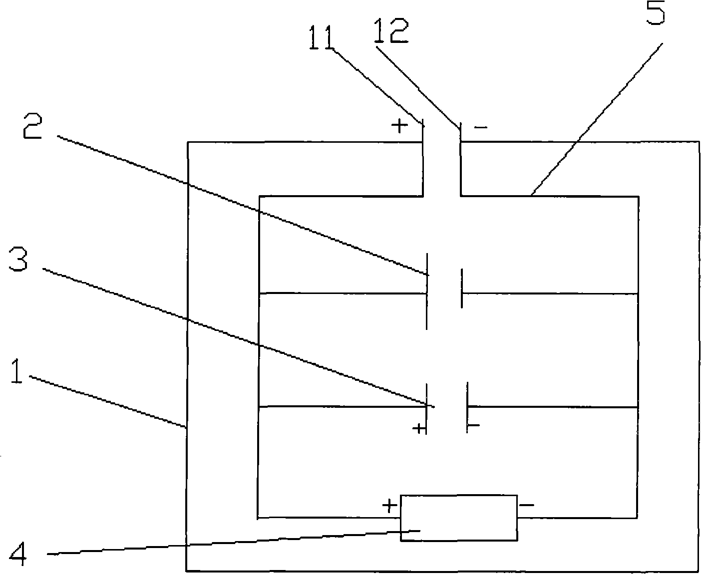
[0066] The embodiment of the present invention also provides the above composite battery preparation method, including the following steps:

[0067] Provide battery case 1, matrix battery 2, supercapacitor 3 and voltage equalizing circuit board 4 respectively;

[0068] Connecting the parent battery 2, the supercapacitor 3 and the equalizing circuit board 4 in parallel to form a parallel system;

[0069] The positive and negative poles of the parallel system are respectively electrically connected to the positive and negative terminals 11 and 12 on the housing 1;

[0070] The mother battery 2, the supercapacitor 3 and the voltage equalizing circuit board 4 after the electrical connection are completed are placed in the battery casing 1 and fixed to obtain the composite battery.

[0071] The steps in the above composite battery preparation method can be appropriately and flexibly adjusted according to actual conditions, such as Figure 8 As shown, the steps are as follows:

...

example 1

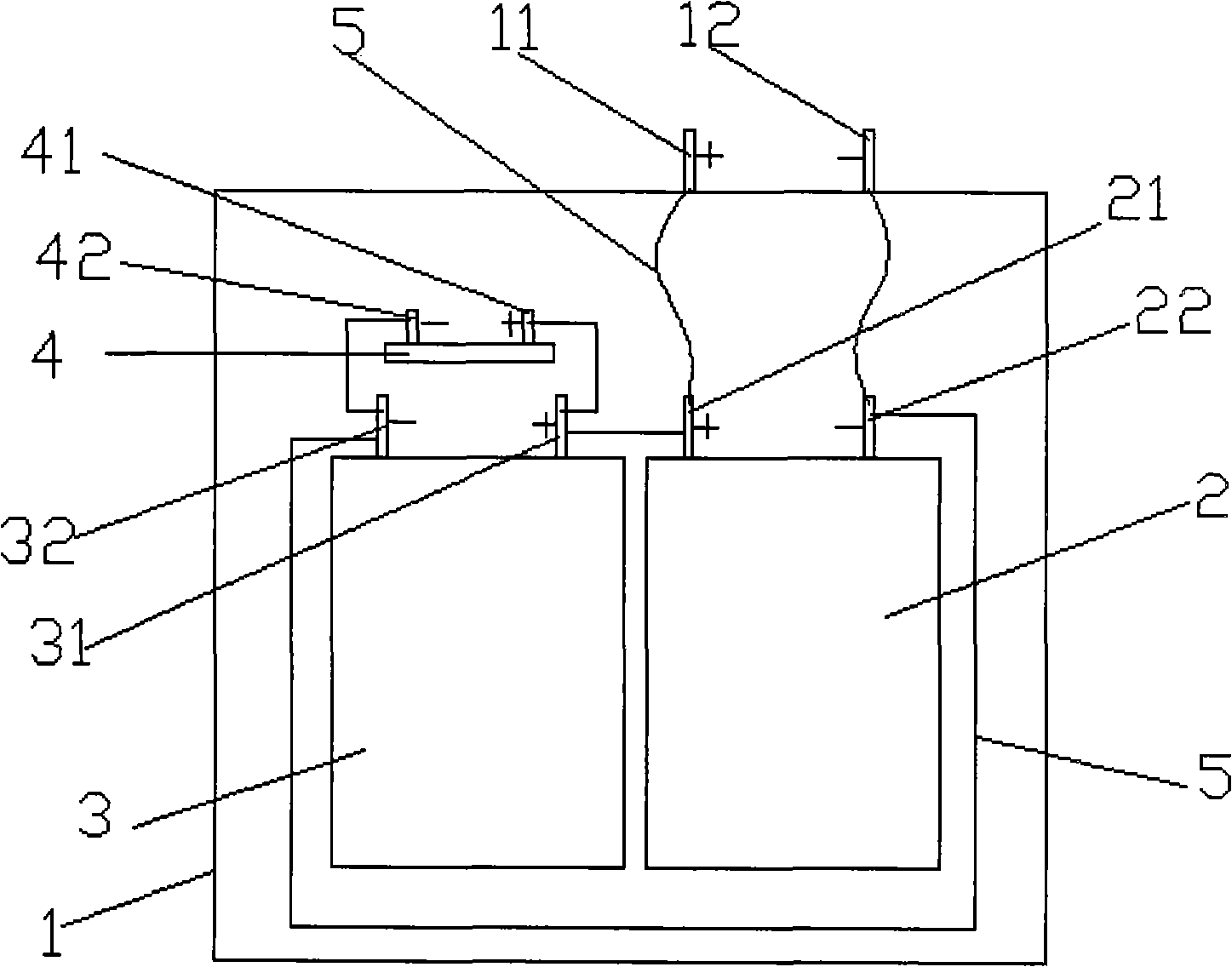
[0104] Such as Figure 4 As shown, the parent battery 2 of the 12V, 100Ah lead-acid battery in the compound battery of this embodiment and the supercapacitor module 3 of 15V~110F are fixed in the inner cavity of the battery case 1, and the voltage equalizing circuit board 4 is welded and screwed 6 Fixed between the positive and negative poles 31 and 32 of the supercapacitor 3, the positive and negative terminals 41 and 42 on the voltage equalizing circuit board 4 are respectively electrically connected to the positive and negative poles 31 and 32 of the supercapacitor 3. , negative poles 31, 32 are respectively electrically connected to the positive and negative poles 21, 22 of the mother battery 2, the positive and negative poles 21, 22 of the mother battery 2 extend outside the battery case 1, and are connected to the positive and negative terminals 11 on the battery case 1 , 12 are integrated, and the electrical connection of each element in this embodiment is connected by ...

example 2

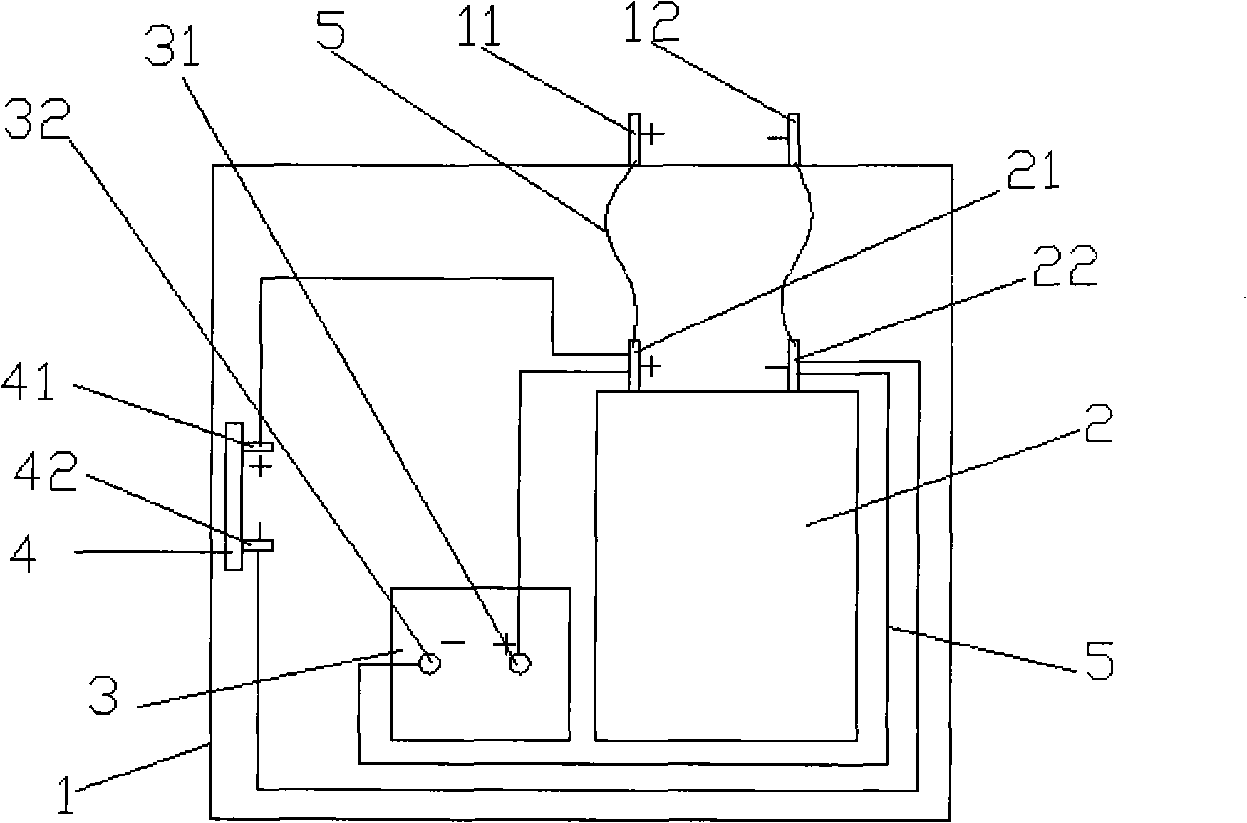
[0121] Such as image 3 As shown, the 24V, 10Ah lithium iron phosphate parent battery pack 2 in the composite battery of this embodiment is vertically fixed in the inner cavity of the battery case 1, and the 27V, 35F supercapacitor module 3 is horizontally fixed in the inner cavity of the battery case 1 At the bottom, the voltage equalizing circuit board 4 is fixed on the side wall of the inner cavity of the battery case 1 close to the super capacitor 3, the positive and negative terminals 41, 42 on the voltage equalizing circuit board 4 and the positive and negative electrodes 31, 32 of the super capacitor 3 The positive and negative poles 21 and 22 of the mother battery 2 are respectively electrically connected to the positive and negative poles 21 and 22 of the mother battery 2, and the positive and negative poles 21 and 22 of the mother battery 2 are respectively electrically connected to the positive and negative terminals 11 and 12 on the battery case 1. The electrical c...


PUM

PropertyMeasurementUnit
Energy densityaaaaaaaaaa

Abstract

The invention discloses a composite battery comprising a battery shell, wherein a positive terminal and a negative terminal are arranged on the battery shell; a matrix battery, a super capacitor and a voltage-sharing circuit board are also arranged in the battery shell; the matrix battery, the super capacitor and the voltage-sharing circuit board are in parallel connection and form electric connection; a positive terminal and a negative terminal on the voltage-sharing circuit board are respectively electrically connected with the anode and the cathode of the super capacitor; the anode and the cathode of the matrix battery are correspondingly and electrically connected with the positive terminal and the negative terminal on the battery shell; and the matrix battery can be a lead-acid battery, a lithium ion battery or a nickel-metal hydride battery. The composite battery has the advantages of high energy and power, low temperature resistance, matrix battery protection, long service life, energy recovery, energy saving and emission reduction, and resource saving, and is applied to electric starting systems, electric drive systems, uninterruptable power output, the starting of tractors and the recovery of the brake energy of motor vehicles. The preparation method has the advantages of simple process and low cost and is suitable for preparing the composite battery of industrial production.

Description

technical field [0001] The invention belongs to the technical field of electrochemistry and chemical power supply, and in particular relates to a composite battery and its preparation method and application. Background technique [0002] The battery industry is an important part of the new energy industry. The new battery technology is one of the high-tech technologies that affect the development of science and technology and industry. It is a sunrise industry with the most development potential in the 21st century. With the advancement of science and technology, the battery industry will play an increasingly important role in national economic construction and national defense construction. [0003] The aggravation of the energy crisis and the increasing number of automobiles make the traditional internal combustion engine vehicles face severe challenges. Especially in China, where the economy is developing at a high speed, oil consumption and imports continue to rise, whi...

Claims


Application Information

Patent Timeline
IPC IPC(8): H01M16/00H01M10/0525H01G9/155H01M10/06H01M10/30H01G11/08
CPCY02E60/124Y02E60/122Y02E60/13Y02E60/126Y02E60/10
Inventor 韩福忠
Owner 韩福忠
Learn More