Direct strong convection board used for hood-type annealing furnace and automatically suitable for cold-rolling strip steel bandwidth and working method thereof

A bell-type annealing furnace and cold-rolled strip technology, applied in furnaces, heat treatment furnaces, manufacturing tools, etc., can solve problems such as inability to improve production efficiency, no improvement in bonding, and single function, so as to reduce ineffective dissipation, temperature Increased consistency, enhanced thermal cycling effect

Inactive Publication Date: 2010-11-24
SHANDONG IRON & STEEL CO LTD
View PDF5 Cites 5 Cited by
  • Summary
  • Abstract
  • Description
  • Claims
  • Application Information

AI Technical Summary

Problems solved by technology

The convection plate effectively avoids the damage and the resulting bonding, but does not improve the bonding caused by uneven temperature, and its function is relatively single, which cannot improve production efficiency

Method used


Image

  • Direct strong convection board used for hood-type annealing furnace and automatically suitable for cold-rolling strip steel bandwidth and working method thereof
  • Direct strong convection board used for hood-type annealing furnace and automatically suitable for cold-rolling strip steel bandwidth and working method thereof
  • Direct strong convection board used for hood-type annealing furnace and automatically suitable for cold-rolling strip steel bandwidth and working method thereof

Examples


Embodiment 1

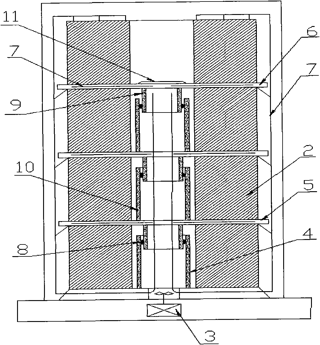
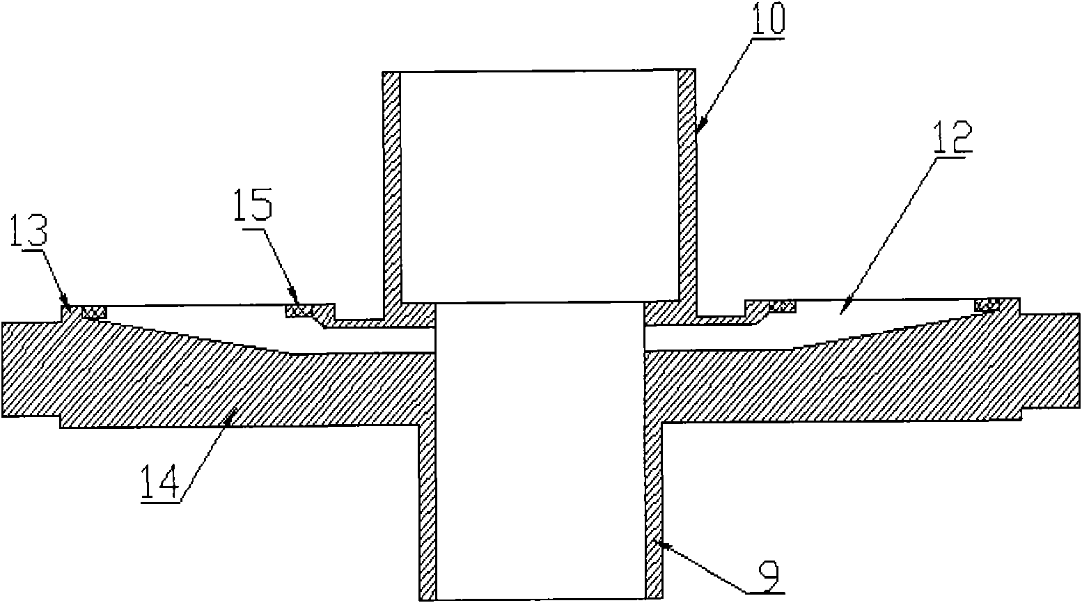
[0047] Such as figure 2 As shown, the four rings of the independent guide pipe are covered with the air outlet of the blower reserved on the hearth, and the length of the upper guide pipe is 100mm smaller than the minimum width of the cold-rolled steel strip that the production line can produce; Stack on the hearth; then place the deflector 5 with the upper and lower deflectors on the first steel coil, and there are 30 radial lines centered on the center of the deflector in the upper half layer of the deflector. Shaped air guide channel (12), the outer diameter of its lower guide tube 9 is 5mm less than the inner diameter of the independent guide tube 4, and the height is 100mm smaller, and the upper guide tube 10 is the same as the inside and outside diameter of the independent guide tube 4, The lengths are the same; the lower draft tube 9 is inserted into the independent draft tube 4 and sealed by a high-temperature-resistant sealing ring 8, wherein the high-temperature-res...

Embodiment 2

[0050] Such as figure 2 As shown, 4 rings of the independent guide pipe are placed on the air outlet of the blower reserved on the hearth, and the length of the upper guide pipe is 50mm smaller than the minimum width of the cold-rolled steel strip that the production line can produce; Stack on the hearth; then place the deflector 5 with the upper and lower deflectors on the first steel coil, and there are 36 radial lines centered on the center of the deflector in the upper half layer of the deflector. Shaped air guide channel (12), the outer diameter of its lower guide tube 9 is 2mm smaller than the inner diameter of the independent guide tube 4, and the height is 50mm smaller, and the upper guide tube 10 is the same as the inside and outside diameter of the independent guide tube 4, The lengths are the same; the lower draft tube 9 is inserted into the independent draft tube 4 and sealed by a high-temperature-resistant sealing ring 8, wherein the high-temperature-resistant se...


PUM


Abstract

The invention relates to a direct strong convection board used for a hood-type annealing furnace and automatically suitable for a cold-rolling strip steel bandwidth and a working method thereof. The direct strong convection board comprises a flow guide pipe and a flow guide plate with a flow guide channel. The direct strong convection board is characterized by the thermal cycle paths of sequentially passing through a heating hood, an inner hood, protective gas inside a furnace after middle temperature rising and convection, an outer ring of a steel coil and a core part of a thermal radiation steel coil in the heating process and sequentially passing through a cooling hood, the inner hood, the protective gas inside the furnace after middle temperature decreasing and convection, the outer ring of the steel coil and the core part of the thermal radiation steel coil in the cooling process. The direct strong convection board fulfills the aims of enforcing middle convection effect and reducing the unbalance of inner and outer temperatures.

Description

technical field [0001] The invention relates to a direct-blowing strong convection plate for a bell annealing furnace capable of automatically adapting to the wide band of cold-rolled strip steel and a working method thereof, belonging to the technical field of metal heat treatment. Background technique [0002] The existing bell-type annealing furnace usually adopts the single-stack tight-coil annealing method, and the steel coils 2 are stacked one by one through the middle convection plate 1 for annealing treatment, see figure 1 . When this traditional method is used for annealing, the convection effect of the middle layer of the steel coil is weakened, and it is easy to cause a temperature difference between the inside and outside during the heating and cooling process, thereby deteriorating the interlayer pressure balance and causing steel sticking. Improve the working efficiency of the bell annealing furnace. At present, many improvement measures and methods have been...

Claims


Application Information

Patent Timeline
Patent Type & Authority Applications(China)
IPC IPC(8): C21D9/673
Inventor 张冠锋许荣昌周俊陵
Owner SHANDONG IRON & STEEL CO LTD
Why Eureka
Try Eureka