Vertical and horizontal efficient energy-saving vacuum controlled atmosphere furnace for continuous production

A vertical-horizontal, atmosphere furnace technology, used in furnaces, muffle furnaces, cooking furnaces, etc., can solve the problems of low equipment space utilization, long cooling time, and inability to continuous production, and improve space utilization and energy utilization. The effect of high efficiency and improved convenience

Inactive Publication Date: 2010-11-24
QINGDAO UNIV OF SCI & TECH +1
View PDF9 Cites 11 Cited by
  • Summary
  • Abstract
  • Description
  • Claims
  • Application Information

AI Technical Summary

Problems solved by technology

The material movement route in the horizontal structure atmosphere furnace is in the horizontal direction, and the vertical structure is in the vertical direction. Such a single movement route causes the overall length of the atmosphere furnace to be too long or the height is too high, and the space utilization rate of the equipment is low, and it is difficult to operate. Inconvenience to personnel, such as patent number "200410022988.8" named "well-type tankless pre-vacuum protection atmosphere furnace", patent number "200610008219.1" named "intermittent atmosphere furnace", patent number "200620160238.1" named The main defects of patents such as "lifting vacuum atmosphere furnace" and patent number "200820078861.1" and "automatic heating and quenching vacuum atmosphere furnace" are: the temperature needs to be raised and lowered repeatedly during the production process, and continuous production is not possible; the heating method is resistance heating, The heating time is long and the heating efficiency is low; the product is cooled with the furnace, the cooling time is long and the production cycle is long

Method used


Image

  • Vertical and horizontal efficient energy-saving vacuum controlled atmosphere furnace for continuous production
  • Vertical and horizontal efficient energy-saving vacuum controlled atmosphere furnace for continuous production
  • Vertical and horizontal efficient energy-saving vacuum controlled atmosphere furnace for continuous production

Examples


Embodiment Construction

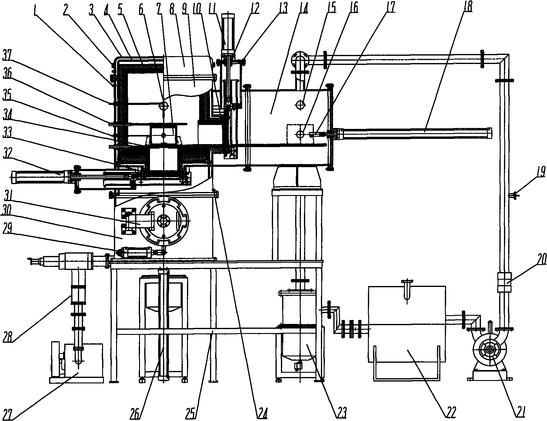
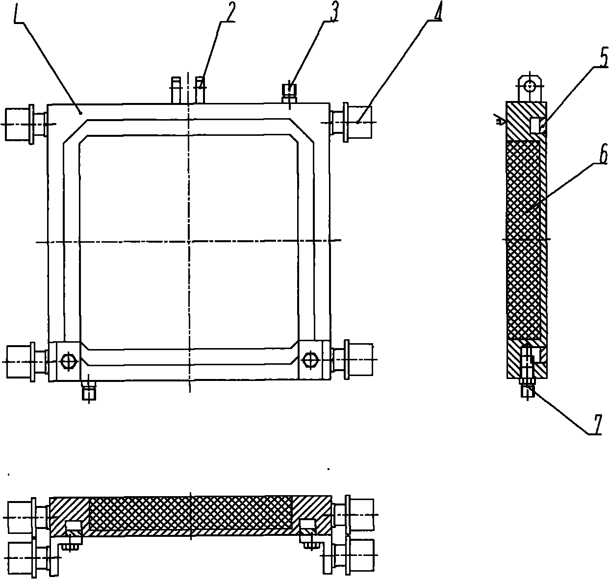
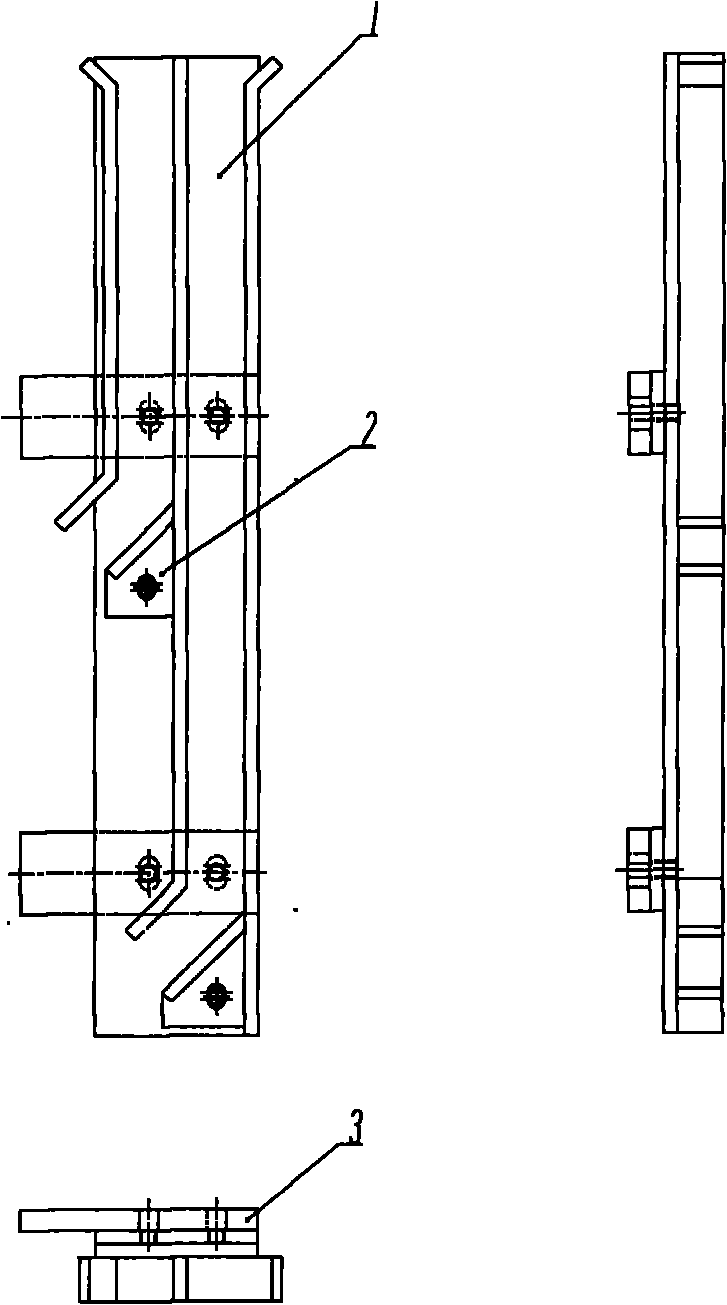
[0027] The present invention will be described in detail below in conjunction with implementation example and accompanying drawing: The vertical and horizontal design in this implementation example is efficient, energy-saving vacuum controllable atmosphere furnace that can be produced continuously, and its structure schematic diagram sees the specification attached figure 1, mainly by water outlet 1, lifting lug 2, outer wall of furnace 3, inner wall of furnace 4, heat insulation layer 5, vacuum pipe 6, 15, carrying box 7, maintenance furnace cover 8, reaction chamber 9, heat preservation sealing door 1 (feeding chamber side) 33, thermal insulation sealing door I gas (hydraulic) pressure cylinder 32, thermal insulation sealing door II (discharging chamber side) 10, thermal insulation sealing door II cylinder 11, oil seal sealing ring 12, "O" type sealing ring 13. Discharge chamber 14, inflatable pipe 16, material pulling rod grab head 17, material pulling cylinder 18, air charg...


PUM


Abstract

The invention aims to provide a vertical and horizontal efficient energy-saving vacuum controlled atmosphere furnace for continuous production with high space utilization rate, high heating speed, high product cooling speed, short production period and avoidance of great energy waste caused by repeated heating and cooling during production. The furnace consists of a feeding chamber, a reaction chamber and a discharge chamber, wherein the feeding chamber is positioned below the reaction chamber, and the feeding chamber and the reaction chamber form a vertical structure; and the discharge chamber is positioned on the lateral surface of the reaction chamber, and the discharge chamber and the reaction chamber form a horizontal structure so as to form a vertical and horizontal structure and improve the space utilization rate. The furnace realizes heat insulation and seal of each chamber by adopting a heat insulation sealing door, and has high heating speed and high energy efficiency by adopting an inductive heating mode; the product is cooled by adopting a circulating air cooling system; and the vertical and horizontal efficient energy-saving vacuum controlled atmosphere furnace for continuous production can perform continuous production only by one-time heating so as to improve the production efficiency, reduce the production cost and save a large amount of energy.

Description

Technical field [0001] The present invention mainly relates to the technical field of nanomaterial synthesis, and also relates to the field of vacuum and atmosphere heat treatment, and relates to a continuous production of nanomaterials by a gas phase method and a vertical and horizontal high-efficiency and energy-saving vacuum furnace for continuous production of vacuum and atmosphere heat treatment and sintering. Controlled atmosphere furnace. Background technique [0002] Nanomaterials are the most dynamic branch of nanotechnology with rich research connotations, and an important foundation for the development of nanotechnology. The American "Business Weekly" listed nanotechnology as one of the three major fields that may make important breakthroughs in the 21st century. The nanomaterials industry is considered to be one of the industries with the most development potential in the 21st century. my country's new nanomaterials market has maintained a growth rate of more tha...

Claims


Application Information

Patent Timeline
Patent Type & Authority Applications(China)
IPC IPC(8): F27B5/05F27B5/06F27B5/14
Inventor 李镇江李孟泽
Owner QINGDAO UNIV OF SCI & TECH
Why Eureka
Try Eureka