Heated structural member thermal shock and thermal fatigue test stand

A test bench, thermal shock technology, used in thermometers, heat measurement, lighting and heating equipment with directly sensitive electrical/magnetic components, etc., can solve the problems of long test cycle and test cost, and shorten the development time. The effect of cycle and saving test cost

Inactive Publication Date: 2010-11-24
ZHEJIANG UNIV
View PDF4 Cites 34 Cited by
  • Summary
  • Abstract
  • Description
  • Claims
  • Application Information

AI Technical Summary

Problems solved by technology

However, the cost of the test is too high and the test cycle is too long, which has great limitations

Method used


Image

  • Heated structural member thermal shock and thermal fatigue test stand
  • Heated structural member thermal shock and thermal fatigue test stand
  • Heated structural member thermal shock and thermal fatigue test stand

Examples


Embodiment Construction

[0028] The specific implementation manner of the present invention will be described in detail below in conjunction with the accompanying drawings.

[0029] 1. The overall composition of the thermal shock and thermal fatigue test bench for heated components

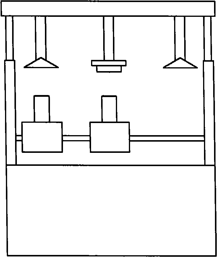
[0030] The test bench is composed of two parts, the test bench and the control system. Its shape is as follows: figure 1 shown. According to the functions, it includes: specimen installation platform and its traveling mechanism, specimen temperature detection system, gas heating system, cooling system, safety and alarm system, control system, monitoring and data storage system, etc.

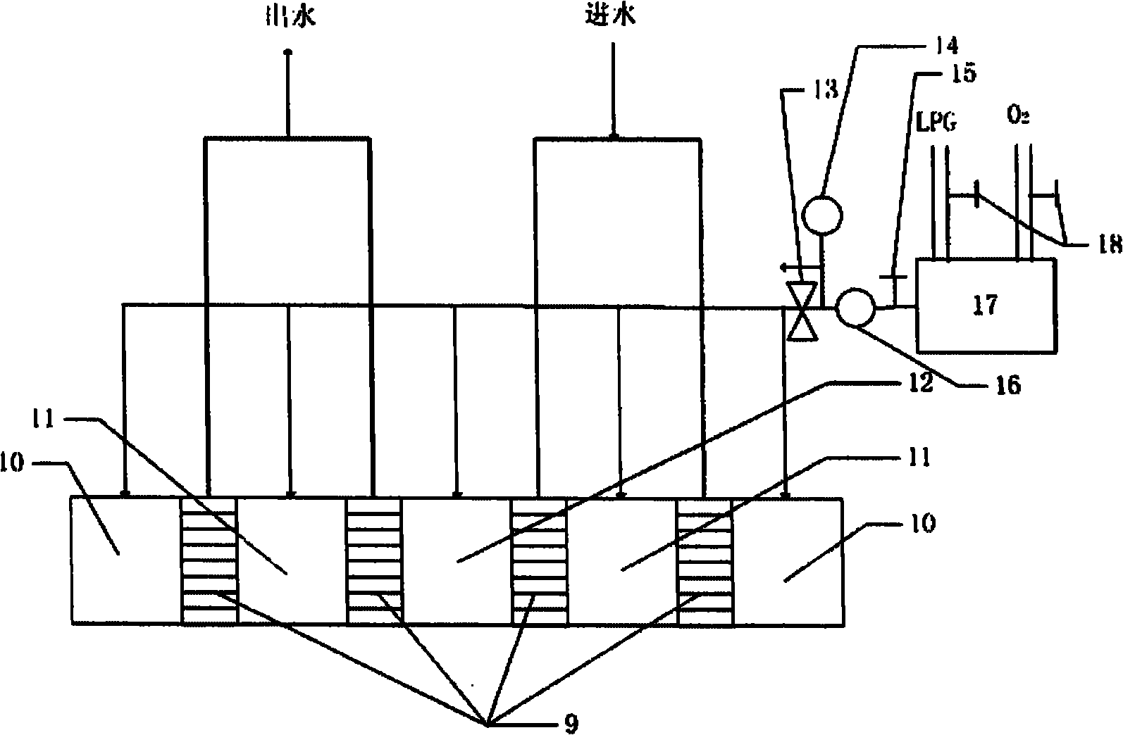
[0031] 2. Introduction of each part of the test bench

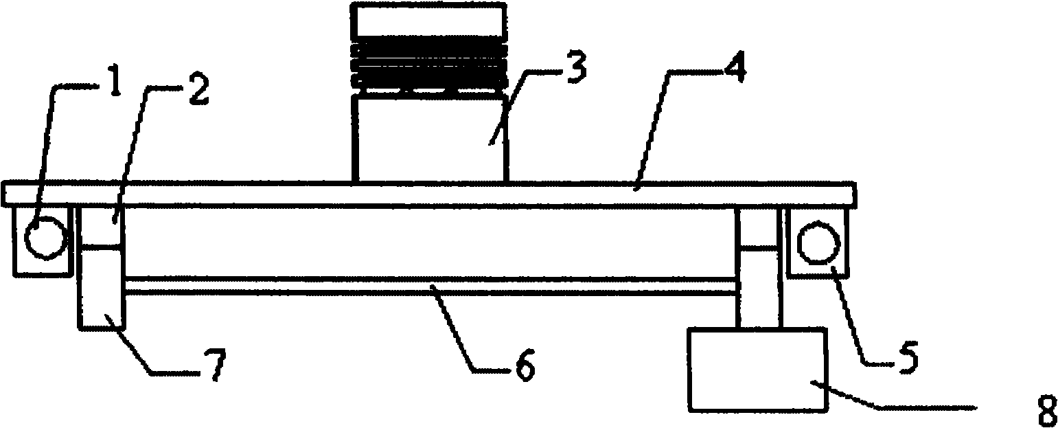
[0032] ·Test piece installation platform and walking mechanism

[0033] Such as figure 2 As shown, the movable test piece installation platform 4 is set on the test bench, and the traveling mechanism is arranged below it; The sleeve 5 and the rack 2 are fixed under the test piece ...


PUM


Abstract

The invention relates to a structural member test unit, aiming at providing a heated structural member thermal shock and thermal fatigue test stand which comprises a movable test bench for a test piece erecting stage, wherein a travelling mechanism is arranged below the test piece erecting stage and comprises a sliding sleeve, a guide rail, a rack, a gear, a transmission shaft and a servo motor; the sliding sleeve and the rack are fixed below the test piece erecting stage, and the guide rail is sleeved in the sliding sleeve; a heating station is arranged on the test bench, and the two sides of the heating station are respectively and symmetrically provided with a cooling station; and a burner of a fuel gas heating system is arranged at the heating station, and each cooling station is provided with a compressed air or cooling water outlet. The invention provides a real machine assessment system which can replace the existing thermal fatigue / thermal shock tests of heated parts such as pistons, cylinder covers and the like; and under the condition of no engine model machine, the heated structural member thermal shock and thermal fatigue test stand can carry out hot strength assessment operation on the heated parts such as pistons, cylinder covers and the like, thus not only saving test expenses but also shortening development period.

Description

technical field [0001] The invention relates to a component test device, in particular to a test bench for thermal fatigue and thermal shock strength assessment of heated components such as engine pistons and cylinder heads. Background technique [0002] With the continuous improvement of engine strengthening, especially the popularization and development of supercharging and other technologies, the thermal load and thermal intensity of engine pistons, cylinder heads and other heated parts have become increasingly prominent, directly affecting the reliability and use of the whole machine. life. During the working process of the engine, most of the heated components are subjected to alternating heat loads, and thermal cracking and burning are more likely to occur. At the same time, in addition to the engine, there are many components and materials that are subjected to alternating heat loads, so the thermal fatigue, Thermal shock performance is of great significance for imp...

Claims


Application Information

Patent Timeline
Patent Type & Authority Applications(China)
IPC IPC(8): G01N3/60G01K7/22F23D14/00F23D14/48
Inventor 刘震涛张宇刘宏瑞沈瑜铭齐放俞小莉
Owner ZHEJIANG UNIV
Why Eureka
Try Eureka