Cyclone separator with grooved wall surface

A technology of cyclone separator and wall surface, which is applied in the direction of cyclone device and the device whose axial direction of the cyclone can be reversed. Particles bounce back to the mainstream area again, and there is no way to raise the flow direction, etc., to achieve the effects of reduced short-circuit flow, reduced wear, and improved separation efficiency

Inactive Publication Date: 2010-12-01
BEIJING INSTITUTE OF PETROCHEMICAL TECHNOLOGY
View PDF14 Cites 9 Cited by
  • Summary
  • Abstract
  • Description
  • Claims
  • Application Information

AI Technical Summary

Problems solved by technology

[0007] Although various technologies disclose slotting or setting baffles at different positions, the importance of particle rebound caused by the wall surface, the swirl instability caused by the Wall Surface Rankine vortex, and the secondary separation of the fine powder in the cylindrical section have not been recognized. Secondary separation and agglomeration of particles actually exist. Therefore, various patents and published documents have not proposed a method of slotting on the wall of the cylinder and following the flow direction of the denser medium.
Various structures in the prior art cannot effectively realize solid particles entering the low-velocity zone near the wall surface in time, and it is also difficult to eliminate the problem that solid particles that have entered the low-velocity zone on the wall surface bounce back to the mainstream zone again

Method used


Image

  • Cyclone separator with grooved wall surface
  • Cyclone separator with grooved wall surface
  • Cyclone separator with grooved wall surface

Examples


Embodiment 1

[0034] Example 1: Cyclone Separator for Fluid Catalytic Cracking Regenerator

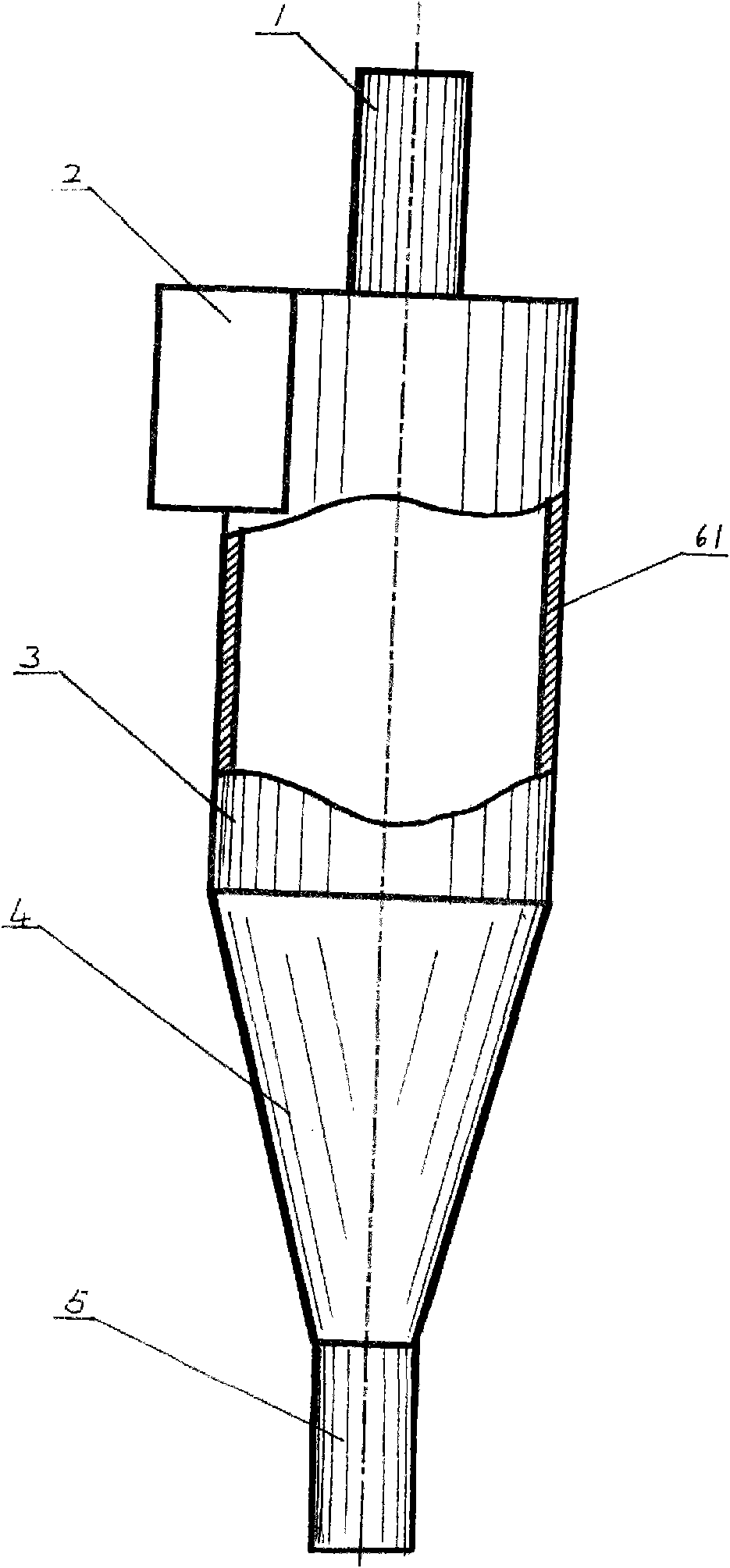
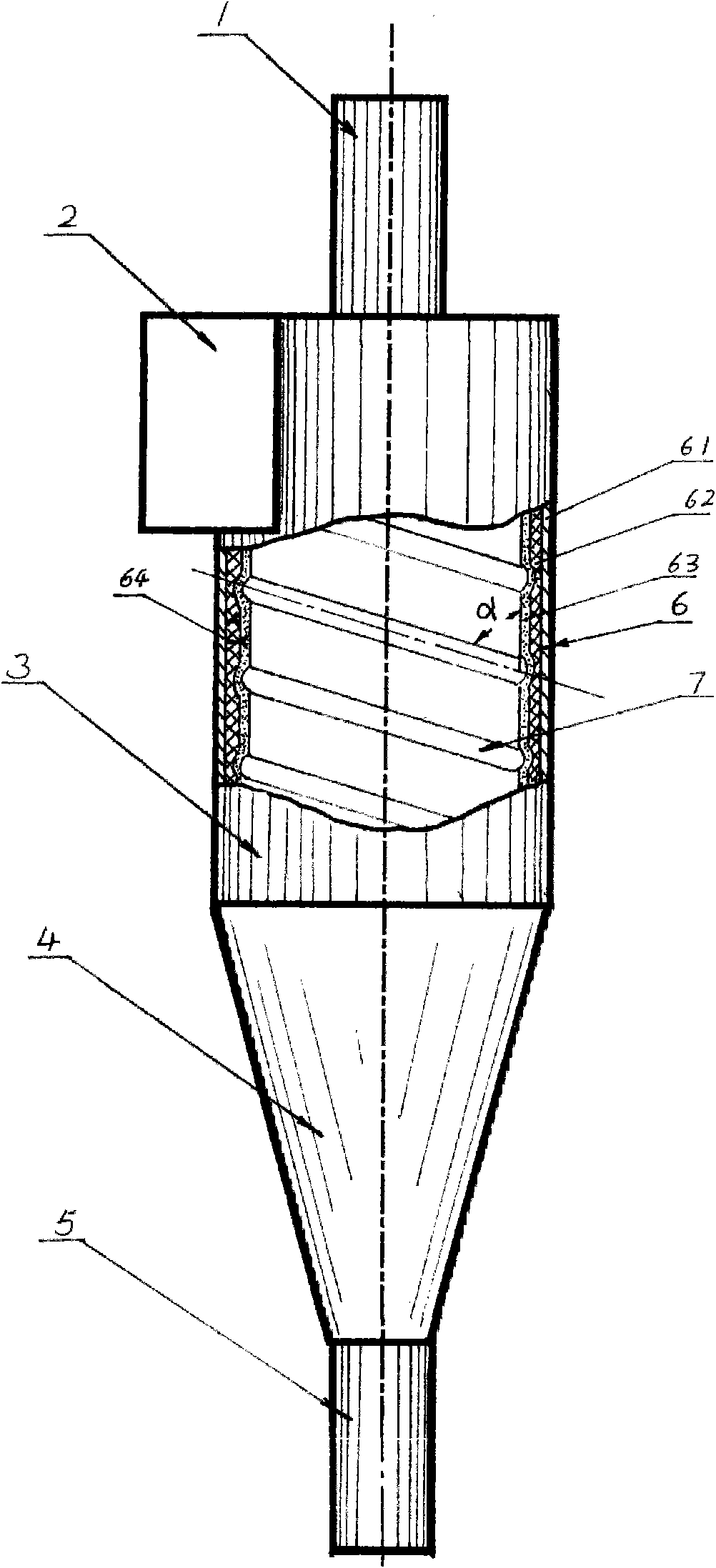
[0035] Depend on figure 2Shown, the cyclone separator with grooved wall surface of the present invention is mainly made up of air riser 1, material system inlet 2, cylinder body 3, cone 4 and tailpipe 5, wherein: air riser 1, material system inlet 2, cylinder The body 3, the cone body 4 and the tailpipe 5 form the whole cyclone separator in order from top to bottom, and a channel 7 is arranged on the wall surface of the inner wall 6 according to the flow direction of the medium with a relatively high density of the material system. Starting at the entrance 2, the channel 7 forms an included angle α of 0-90°C with the direction of fluid flow, and the ratio of the area of ​​the channel 7 to the wall surface swept by the fluid is 0-0.9.

[0036] Grooves are made on the wall of the cyclone separator along the particle flow direction, and the inner wall 6 and the channel 7 are channels formed by pressi...

Embodiment 2

[0043] Example 2: Cyclone Separator after Combustion in Circulating Fluidized Bed

[0044] In the pulverized coal circulating fluidized bed combustion boiler system, the cyclone separator is the most important unit equipment. Relying on the efficient operation of the cyclone separator, the reduction of boiler unburned loss and the improvement of boiler efficiency can be realized. When used in the coal combustion process, the flue gas and unburned coal powder at high temperature enter the cyclone separator, and the lining 63 of the cyclone separator will prevent the wall surface of the metal outer wall 61 from directly contacting the high temperature medium. damage its strength. The mixture enters from the entrance 2 of the system and flows downward in rotation. The pulverized coal and ash will be separated and thrown to the wall and enter the channel 7 formed by the lining 63, and flow spirally downward along the channel 7. When the flow approaches the tail pipe At 5 o'clock...

Embodiment 3

[0046] Embodiment 3: cyclone separator

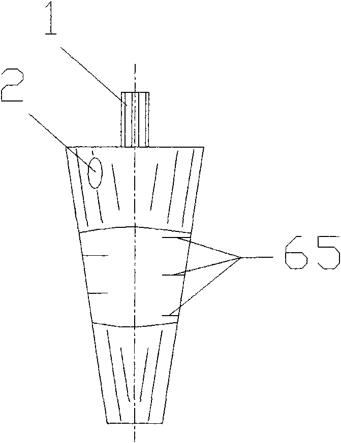
[0047] One of the important equipment for processing oilfield production fluid is cyclone separator, especially for offshore oil platforms with small space, efficient and compact cyclone separator is an important equipment to improve the working efficiency of offshore oil platforms, as described here The structure and working principle of the cyclone separator is similar to that of the cyclone separator. The structure for separating gas-solid heterogeneous systems is generally called a cyclone separator; for the separation of liquid-solid or gas-liquid heterogeneous The structure of the phase system is generally called a cyclone separator or a cyclone.

[0048] On the wall surface of the cyclone, intermittent channels are opened along the flow direction of the particles, and the inner wall 6 and the channel 7 are formed by milling along the spiral direction on the wall. The diameter of the cyclone separator is 100mm, the cross section ...


PUM


Abstract

The invention relates to a cyclone separator with a grooved wall surface for heterogeneous system separation, which mainly and sequentially comprises a riser (1), a system inlet (2), a cylinder body (3), a cone body (4) and a tail pipe (5) from top to bottom, wherein a groove channel (7) is arranged on an inner wall (6) according to a medium flowing direction with larger system density, the groove channel (7) forms an alpha angle with a fluid flowing direction, and the cross section of the groove channel (7) is in a semicircular shape, an arc shape, a triangular shape or other geometrical shapes. The invention has the advantages of simple structure, convenient construction and large operation elasticity, is easy to reform the original structure, can obviously reduce cutting grain diameter sizes and greatly increases heterogeneous separation efficiency.

Description

technical field [0001] The invention relates to a machine for separating media with different densities by centrifugal force, in particular to a cyclone separator which uses centrifugal force generated by the medium to separate solid particles contained in gas or liquid by opening a channel on the wall of the separation device. Background technique [0002] It is well known that an important method of separating heterogeneous systems is the use of so-called cyclones (for gas-solid or gas-liquid systems) or cyclones (for liquid-solid, liquid-liquid or gas- liquid system). The heterogeneous system enters the separation device at a certain speed, and the fluid medium is constrained by the geometric components to produce rotational motion. Since the different phases in the heterogeneous system have density differences, the resulting centrifugal force of different sizes drives each material to separate. The system produces separation in the geometric space, and then the differen...

Claims


Application Information

Patent Timeline
Patent Type & Authority Applications(China)
IPC IPC(8): B04C5/103
Inventor 雷俊勇戴静君刘录孟波
Owner BEIJING INSTITUTE OF PETROCHEMICAL TECHNOLOGY
Why Eureka
Try Eureka