Modification processing method of optical element surface and numerical control machine used thereby

A processing method and technology of optical components, which are applied to optical surface grinders, metal processing equipment, grinding machines, etc., can solve the problems of complex calculation of the rotation axis 21 and high requirements on the CNC system of the machine tool, and achieve simple residence time and good controllability. , The effect of low requirements on processing equipment

Active Publication Date: 2012-05-30
NAT UNIV OF DEFENSE TECH
View PDF0 Cites 5 Cited by
  • Summary
  • Abstract
  • Description
  • Claims
  • Application Information

AI Technical Summary

Problems solved by technology

However, for a workpiece with a high steepness, if the rotation axis 21 parallel to the optical axis is always used to exert pressure on the surface of the workpiece 9, since the angle change of the curved surface of the workpiece 9 has a non-negligible influence on the removal function, it is still required that the machine tool has five degrees of freedom. This not only has high requirements on the structure of the machine tool and the numerical control system, but also the calculation of the position coordinates of each processing point on the surface of the workpiece 9 and the offset angle of the rotation axis 21 are relatively complicated.

Method used


Image

  • Modification processing method of optical element surface and numerical control machine used thereby
  • Modification processing method of optical element surface and numerical control machine used thereby
  • Modification processing method of optical element surface and numerical control machine used thereby

Examples


Embodiment

[0048] Using the method for modifying the surface of an optical element of the present invention to process a workpiece to be processed comprises the following steps:

[0049] 1. Planning the processing and scanning route

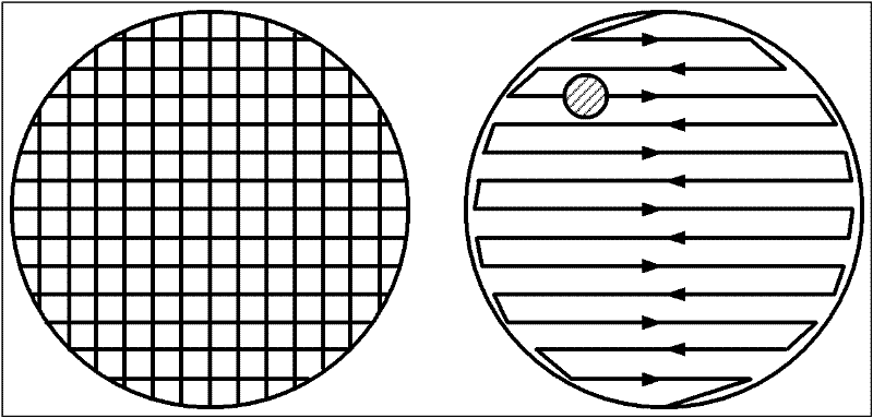
[0050] 1.1 Take a workpiece to be processed, take the center of the workpiece as the coordinate origin, and establish an X-Y rectangular coordinate system; then according to the size of the workpiece, use a square grid composed of intersecting lines parallel to the coordinate axis and equally spaced (each small unit The side length of the grid is about 10mm) to discretize the workpiece into several processing points S; the coordinates of each processing point on the workpiece are marked as S(x i ,y i ), where x i and y i Represents the position of each point on the workpiece in the discrete grid; the discretized surface of the workpiece is as attached Figure 5 shown.

[0051] 1.2 Connect all the processing points with a number of parallel lines parall...


PUM


Abstract

The invention discloses a modification processing method of an optical element surface, comprises the following steps: planning a processing and scanning route, converting coordinates, calculating processing dwell time, modifying and processing, converging step by step and the like, is combined with the advantages of an X-Y scanning mode and a rho-theta scanning mode, has the advantages of good stability, strong controllability, simple processing operation and high processing precision, and is especially suitable for the modification processing of the optical element surface of a high gradient workpiece. The invention also discloses a numerical control machine used in the modification processing method, an abrasive disk thereof and a rotation axis thereof are connected with a universal coupling, the rotation axis of a removal function generator is aslant arranged on an engine base in a mode of having an included angle beta with the optical axis of a workpiece to be processed, and the numerical control machine has the advantages of simple structure, low cost and the like.

Description

technical field [0001] The invention relates to the technical field of optical element processing, in particular to a method for modifying the shape of an optical element and numerical control processing equipment used for the method. Background technique [0002] At present, computer-controlled optical surface shaping technology (CCOS technology) has been widely used in the ultra-precision machining of medium and large-diameter high-steep optical components. Compared with traditional manual polishing technology, its processing efficiency and processing accuracy are higher. CCOS technology refers to the use of a tool that is much smaller than the workpiece (which can be referred to as a small tool) to move on the surface of the optical element at a specific path and speed under computer control, by controlling the residence time and processing pressure in each area. and other parameters to precisely control the amount of material removal on the surface of the optical element...

Claims


Application Information

Patent Timeline
Patent Type & Authority Patents(China)
IPC IPC(8): B24B13/00
Inventor 郑子文戴一帆李圣怡舒勇彭小强陈善勇
Owner NAT UNIV OF DEFENSE TECH
Why Eureka
Try Eureka