Condensation recycling method and device of unloading tail gas-naphtha

A technology for condensation recovery and oil unloading, which is applied in the petroleum industry, liquid hydrocarbon mixture recovery, etc., can solve the problems of safety hazards, large installation space, poor recovery effect, etc., and achieves obvious economic and environmental benefits and saves money. Directly draining cooling water, small change effect

Inactive Publication Date: 2010-12-01
PETROCHINA CO LTD
View PDF7 Cites 4 Cited by
  • Summary
  • Abstract
  • Description
  • Claims
  • Application Information

AI Technical Summary

Problems solved by technology

When the inlet of the submersible pump at the bottom of the tanker is exposed to the oil surface, start the vacuum pump to pump the residual naphtha at the bottom of the tanker into the vacuum tank, and the exhaust gas of the vacuum pump is generally directly discharged into the atmosphere, resulting in a large space in the device within a certain period of time, the concentration of oil and gas is relatively large, and the environmental pollution is relatively serious
The exhaust gas of the vacuum pump is a flammable gas, and the alarm often sends out an alarm. Thunder in summer can easily cause the device to flash, which brings great safety hazards to safe production work and wastes resources.
Later, the exhaust gas of the vacuum pump was recovered by water cooling, but this method was limited by the low temperature environment, and the water consumption was large, so the recovery effect was poor

Method used


Image

  • Condensation recycling method and device of unloading tail gas-naphtha
  • Condensation recycling method and device of unloading tail gas-naphtha

Examples


Embodiment 1

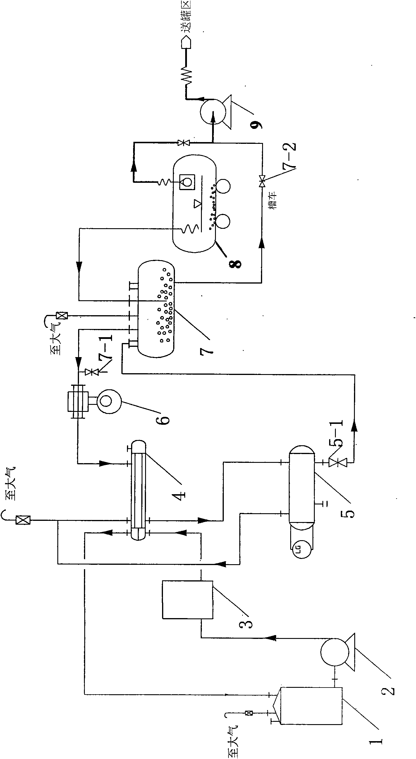
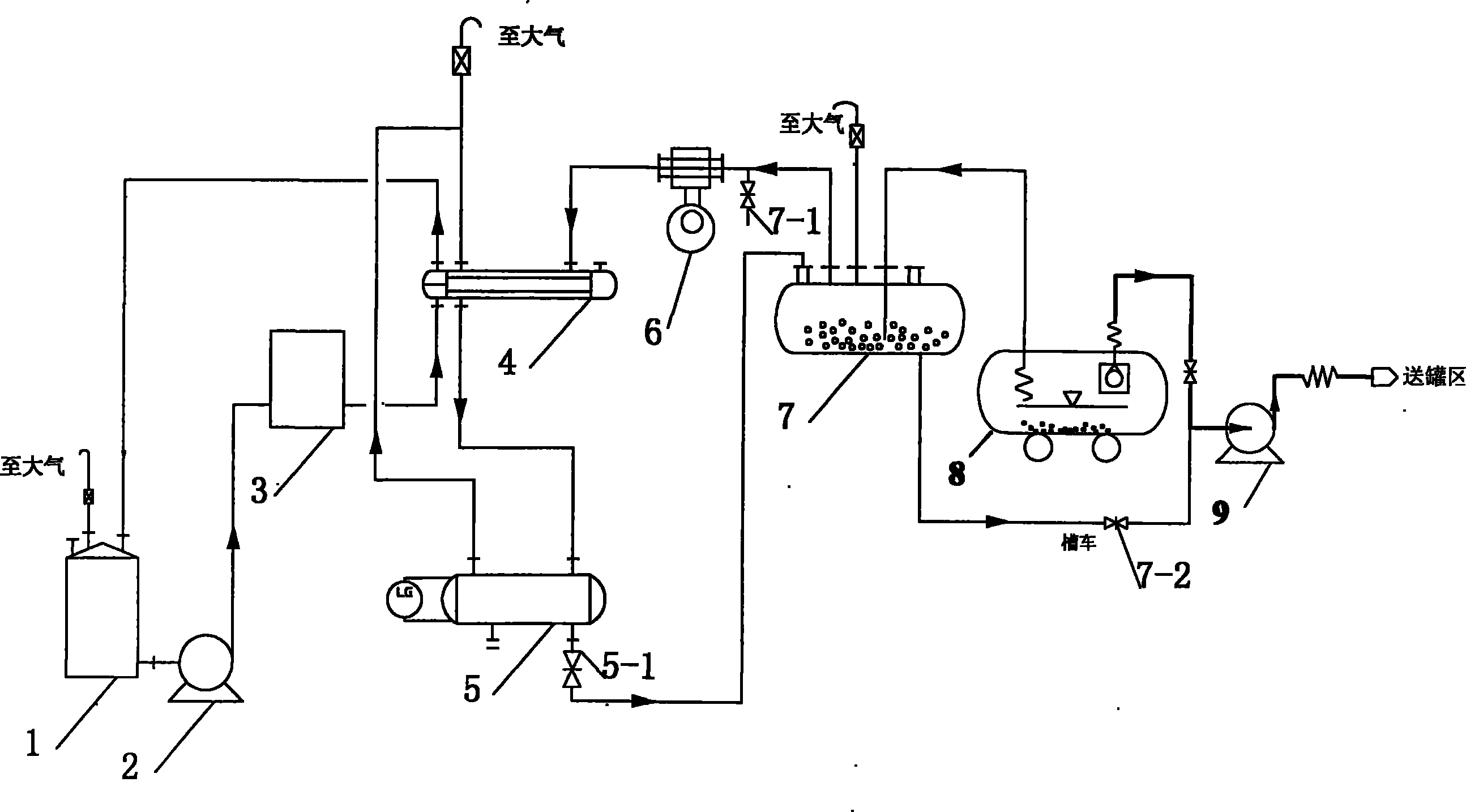
[0019] As can be seen from the accompanying drawings, the naphtha unloading tail gas condensation recovery device of the present invention mainly contains a vacuum pump 6, a vacuum tank 7, a condensate recovery tank 5, a condenser 4, and a flame arrester. There is an ice machine 3 connected through a pipeline, and the inlet of the circulation pump 2 is connected with the condensing medium ethylene glycol storage tank 1 through a pipeline to form a closed circulation system of condensing medium ethylene glycol solution, which is safe and environmentally friendly. The condensate recovery tank 5 is connected to the flame arrester through a pipeline, and the flame arrester is connected to the atmosphere, and the condensate recovery tank 5 is connected to the pipeline below the flame arrester through a pipeline, so as to prevent fire accidents caused by lightning.

Embodiment 2

[0021] As can be seen from the accompanying drawings, the naphtha unloading tail gas condensation recovery method is composed of the following steps:

[0022] (1) After the stand-alone water test run of the condensing closed-circuit circulation system is normal, add desalted water and ethylene glycol as the condensing medium to the condensing medium storage tank to prepare a ethylene glycol solution with a volume percentage concentration of 60-80%, open the inlet valve of the circulating pump, and start Circulation pump, when the outlet pressure of the circulation pump reaches 0.4-0.6MPa and is stable, slowly open the outlet valve of the circulation pump. When the outlet pressure of the ice machine is stable at 0.4-0.6MPa, the ethylene glycol solution enters the condenser from its storage tank through the ice machine , and then return to the ethylene glycol storage tank to form a closed-circuit circulation system of ethylene glycol solution; start the ice machine, the temperatu...


PUM


Abstract

The invention provides a condensation recycling method and device of unloading tail gas-naphtha. The method comprises the following steps: starting a circulating pump to return a condensation medium-glycol solution to a glycol storage tank via a refrigerating machine and a condenser; a naphtha tank car entering into a platform to be in para position with a loading arm and then transferring naphtha to an oil storage tank via a submersible pump at the inlet of the loading arm and an unloading oil pump; starting a vacuum pump to absorb the residual naphtha in the tank car into a vacuum tank whenthe tank car oil level is lower than the inlet of the submersible pump; opening an outlet valve of a condensate recycling tank to absorb the recycled condensate into the vacuum tank when the condensate is 1 / 2-2 / 3 of the recycling tank by volume; and stopping the vacuum pump, opening an outlet value of the vacuum tank and transferring the naphtha and the condensate in the vacuum tank to the oil storage tank by the unloading oil pump.

Description

technical field [0001] The invention relates to a method and a device for recovering naphtha unloading tail gas, in particular to a method for condensing and recovering naphtha unloading tail gas and a required device. Background technique [0002] At present, the naphtha used in the ethylene plant is transported to the unloading platform by tank trucks, and the naphtha in the tank trucks is pumped to the tank area of ​​the oil product workshop through oil pumps. When the inlet of the submersible pump at the bottom of the tanker is exposed to the oil surface, start the vacuum pump to pump the residual naphtha at the bottom of the tanker into the vacuum tank, and the exhaust gas of the vacuum pump is generally directly discharged into the atmosphere, resulting in a large space in the device Within a certain period of time, the concentration of oil and gas is relatively high, which causes serious environmental pollution. The exhaust gas of the vacuum pump is a flammable gas, ...

Claims


Application Information

Patent Timeline
Patent Type & Authority Applications(China)
IPC IPC(8): C10G5/06
Inventor 殷丽文刘庆龙刘红扬刘宏吉高大鹏周剑宇孙明峰
Owner PETROCHINA CO LTD
Why Eureka
Try Eureka