Method for replacing shield cutter in sand-pebble layer

A shield cutting tool and cutting tool replacement technology, which is applied in the direction of earth drilling, mining equipment, tunnels, etc., can solve problems such as subsidence, soil cutting, crushing obstruction, and impact on mechanical equipment, so as to achieve self-reliance and reduce soil adhesion. , the effect of easy operation

Active Publication Date: 2010-12-01
SHANGHAI TUNNEL ENG CO LTD
View PDF0 Cites 21 Cited by
  • Summary
  • Abstract
  • Description
  • Claims
  • Application Information

AI Technical Summary

Problems solved by technology

[0007] (1) After the tool is worn, it cannot effectively cut the soil and break the rock, and the soil cannot enter the soil bin smoothly
[0008] (2) After the local tool is worn, the corresponding cutting and crushing loads of other tools increase, which accelerates the wear of other tools
[0009] (3) Increase the burden on the cutter head. After the contact between the cutter, the cutter head and the soil changes from the original line contact to the surface contact, the friction coefficient increases, and the cutter head torque needs to be increased accordingly to adapt to the increase in frictional resistance, resulting in The current consumption and oil pressure load increase, the frequency of mechanical failures is high, and the life of mechanical equipment is shortened
[0010] (4) After the tool protecting the cutterhead is worn out, the cutterhead directly contacts with high-strength pebbles, causing the cutterhead to wear out, affecting the mechanical equipment inside and behind the cutterhead p...

Method used


Image

  • Method for replacing shield cutter in sand-pebble layer
  • Method for replacing shield cutter in sand-pebble layer
  • Method for replacing shield cutter in sand-pebble layer

Examples


Embodiment Construction

[0025] Further details will be given below in conjunction with specific engineering examples on which the present invention is based.

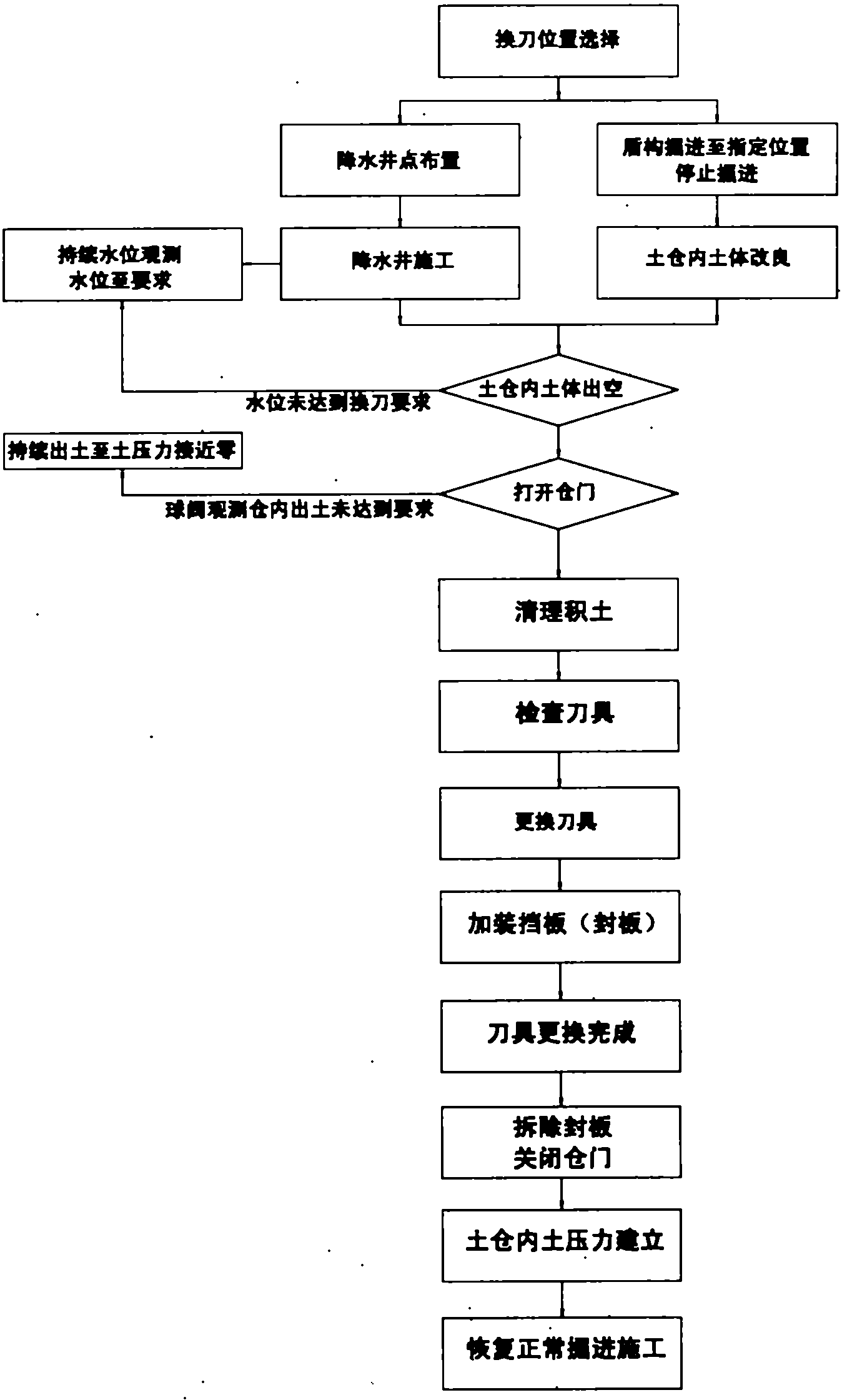
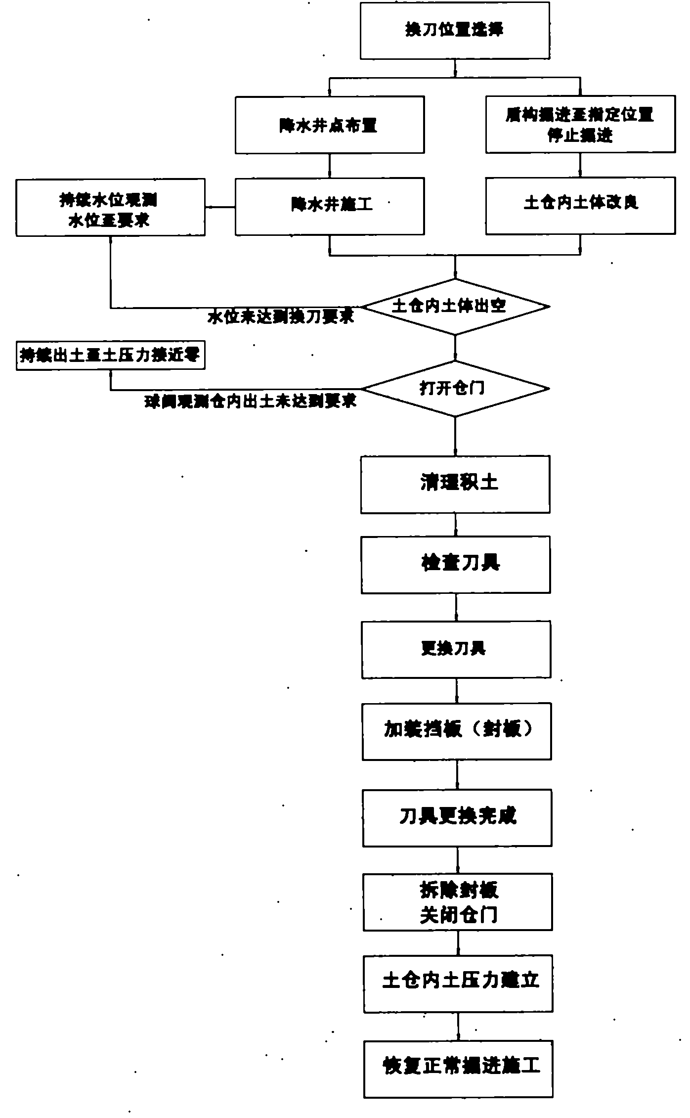
[0026] refer to figure 1 Shown, method of the present invention mainly comprises the following steps:

[0027] a. Preparation steps before tool replacement, including:

[0028] (1). Select the tool change position;

[0029] Before the tool change, the position of the tool change must be systematically considered. The selection of the tool replacement position is mainly based on the following principles:

[0030] a. The material and performance parameters of the tool determine the service life of the tool, which is converted into the corresponding tunneling mileage according to the service life of the tool;

[0031] b. Fully consider the feasibility and convenience of the implementation of ground reinforcement (precipitation construction) measures;

[0032] c. Avoid areas with complex surrounding environments, such as areas with many build...


PUM


Abstract

The invention provides a method for replacing a shield cutter in a sand-pebble layer, which comprises the following steps: a, preparation steps before replacing the cutter are as follows: (1) selecting a position for replacing the cutter; (2) establishing a dewatering well to cause a shield cut position to completely be in the range of a drawdown curve; and (3) modifying soil mass in a soil storehouse, carrying out grouting on the upper part of a shield shell, pressing and injecting oil greases for a shield tail, dredging and washing grouting pipelines; b, steps for replacing the cutter are as follows: (1) carrying out dewatering construction and emptying the soil mass in the soil storehouse when the water level in the dewatering well reaches the required water level; and (2) installing a blanking plate in an empty position between the two pairs of cutter heads, rotating the cutter heads and performing replacement of the curter; and c, steps for recovering tunneling after replacing the cutter are as follows: (1) dismantling the blanking plate, closing the door of the soil storehouse and injecting inert serous fluid into the soil storehouse until soil pressure reaches the set soil pressure; and (2) recovering the tunneling. By utilizing the method, timely and effective replacement of worn cutters in the sand-pebble layer can be realized and the operation is relatively simple and safe.

Description

technical field [0001] The invention relates to a method for replacing a shield cutter, in particular to a method for replacing a shield cutter in a sandy pebble formation. Background technique [0002] The compound earth pressure balance shield machine is specially designed for tunnel construction for sand and pebble strata. It mainly uses the cutter on the cutter head panel to effectively cut and break the sand and pebble soil in front of the cutter head. Under the premise of soil improvement measures, a good entry and discharge channel is formed inside the shield machine, so that the shield tunnel can move forward smoothly, and can effectively reduce ground subsidence and its impact on the surrounding environment. [0003] At present, the cutters configured on the compound earth pressure balance shield machine mainly have the following forms, and the corresponding functions are shown in Table 1: [0004] [0005] [0006] The above shield cutting tools are all base...

Claims


Application Information

Patent Timeline
IPC IPC(8): E21D9/06
Inventor 彭建成顾春华阮关荣卓发成魏新良陈年红刘喜东
Owner SHANGHAI TUNNEL ENG CO LTD
Why Eureka
Try Eureka