Method for digitally driving and detecting multi-gauge head gyroscope

A driving method and gyro technology, which are applied in the direction of gyro effect for speed measurement, gyro/steering sensing equipment, measuring device, etc., can solve the problems of poor stability of the resonant frequency deviation system of the gyro head, etc.

Inactive Publication Date: 2010-12-01
NORTHWESTERN POLYTECHNICAL UNIV
View PDF4 Cites 18 Cited by
  • Summary
  • Abstract
  • Description
  • Claims
  • Application Information

AI Technical Summary

Problems solved by technology

But there are also shortcomings: the system stability is poor when the resonant frequency deviation of the gyro head is large

Method used


Image

  • Method for digitally driving and detecting multi-gauge head gyroscope
  • Method for digitally driving and detecting multi-gauge head gyroscope
  • Method for digitally driving and detecting multi-gauge head gyroscope

Examples


Embodiment Construction

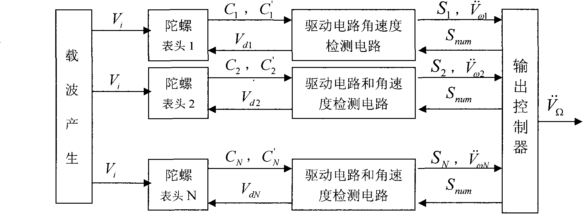
[0059] In this example, the number N of micromechanical gyroscope heads is 3, and the values ​​of n are 1, 2, 3. The resonant angular frequency range of the three gyro heads ω xmin to ω xmax , where ω xmin = 2π·2990rad / s, ω xmax =2π·3010rad / s. The quality factor of the gyroscope is Q x =1000, m x =m y =10 -6 Kg, driving force F 0 =10 -6 N, the carrier frequency is 100KHz. The phase control word of the digital NCO is 32 bits, and the clock frequency is F clk 1MHz. The digital signal processing chip is FPGA. The sampling frequency of A / D and D / A conversion is 1MHz, and the number of sampling bits is 16 bits.

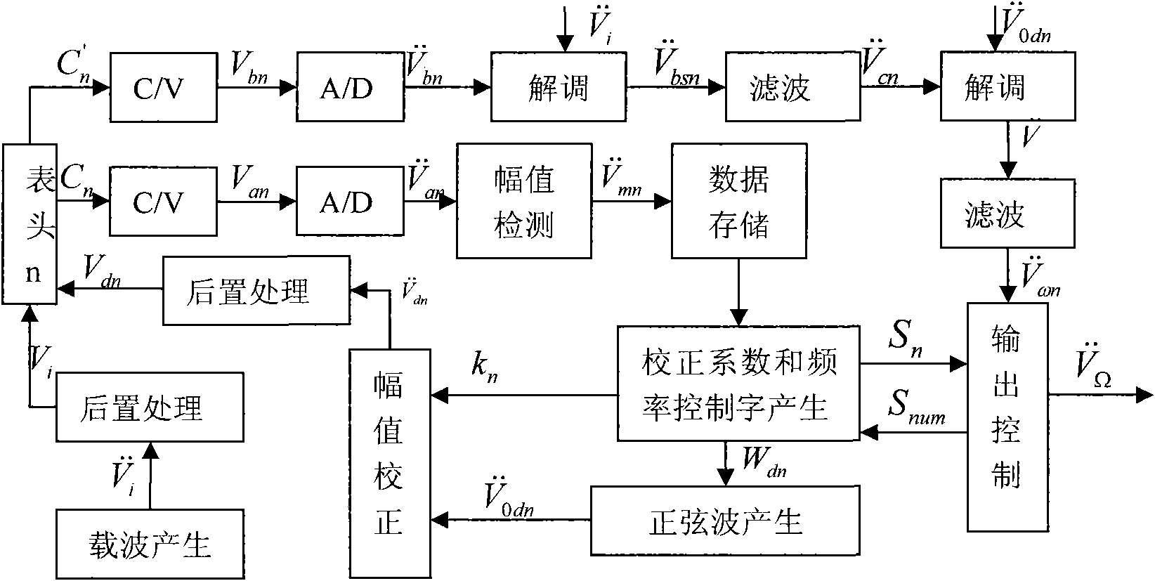
[0060] The specific implementation is divided into two parts: gyro drive and angular velocity detection:

[0061] A multi-meter gyroscope digital driving method, comprising the following steps:

[0062] Step 1: Load the carrier signal V on the gyro head n i and drive signal V dn , the gyro head will vibrate in the X direction after the signal is loaded, an...


PUM


Abstract

The invention discloses a method for digitally driving and detecting a multi-gauge head gyroscope, and belongs to the field of micro-mechanical gyroscope signal processing. The method comprises the following steps of: generating a carrier wave Vi by a digital method, simultaneously generating drive signals Vd1, Vd2,..., and VdN by a drive circuit, and loading the carrier wave Vi and the drive signals Vd1, Vd2,..., and VdN on the gauge head 1, the gauge head 2,..., and the gauge head N of the gyroscope in sequence, wherein N is more than or equal to 2; detecting drive mode capacitors C1, C2,..., and CN, adjusting the drive signals Vd1, Vd2,..., and VdN according to the detected signals so as to make the N gauge heads of the gyroscope work at resonance points; and based on the driving of the gyroscope, detecting sensitive mode capacitors C'1, C'2,..., and C'N, obtaining N angular velocity signals of the gyroscope, and according to N frequency sweeping states S1, S2,..., and SN of the gyroscope, processing the detected angular velocity signals and outputting the final angular velocity by a controller. The method is mainly characterized by locking the resonance frequency by a method of detecting the amplitude of the drive output signal by sweep frequency and has the advantages of the realization of self correction, high frequency stability and high anti-interference ability.

Description

1. Technical field [0001] The invention relates to a multi-head gyroscope digital driving and detection method, which belongs to the field of micromechanical gyroscope signal processing. 2. Background technology [0002] Micromachined gyroscopes are typical inertial devices. Compared with traditional mechanical gyroscopes, fiber optic gyroscopes and laser gyroscopes, it has the advantages of small size, light weight, low power consumption, fast start-up, low cost, high reliability and easy digitization, so its application range is rapidly expanding and can be used It is used in various aspects such as car anti-rollover, flight attitude control, satellite attitude control, camera anti-shake, car navigation system, and micro drones. The gyroscope circuit is an important part of the micromachined gyroscope. Traditional analog circuits, due to the characteristics of analog devices, inevitably introduce temperature drift, and it is difficult to accurately realize self-calibrati...

Claims


Application Information

Patent Timeline
Patent Type & Authority Applications(China)
IPC IPC(8): G01C19/56G01C19/5776
Inventor 常洪龙李小卿李慧敏赵海涛丁继亮吕湘连王玉朝
Owner NORTHWESTERN POLYTECHNICAL UNIV
Why Eureka
Try Eureka