Beam down system solar generation device

A technology of solar thermal power generation and solar light, which is applied in the direction of solar thermal devices, solar thermal power generation, heating devices, etc., can solve the problems of central reflector 110 skew or offset, low endurance, and inability to improve strength, etc., and achieve lightening Effects of blocking phenomenon and shadowing phenomenon, improvement of shock resistance and strength, and prevention of shifting of the optical axis

Inactive Publication Date: 2010-12-01
MITSUI ENG & SHIPBUILD CO LTD
View PDF3 Cites 7 Cited by
  • Summary
  • Abstract
  • Description
  • Claims
  • Application Information

AI Technical Summary

Problems solved by technology

[0015] Therefore, the pillars 100a, 100b, and 100c vertically erected without reinforcing members between the pillars have extremely low resistance to the rotational force F in the circumferential direction of the central reflector 110, and in addition, there is wind resistance or earthquake lateral load resistance. Bad problem, the load load of each pillar is large
[0016] In addition, the fixing places that each support has are the fixing portion 112 of the central reflector 110 on the upper end side and the anchors (anchor) 115a, 115b, 115c on the lower end side of the support, and the stability and strength of the support cannot be obtained. Structure
Therefore, there is a problem of safety, a problem of durability, and a problem of shifting the optical axis by causing the center reflector 110 to be skewed or shifted.
[0017] Furthermore, if the number of pillars is increased in order to improve the strength, blocking and shadowing will occur, resulting in a decrease in power generation efficiency, so there is a problem that the strength cannot be improved.

Method used


Image

  • Beam down system solar generation device
  • Beam down system solar generation device
  • Beam down system solar generation device

Examples


Embodiment 1

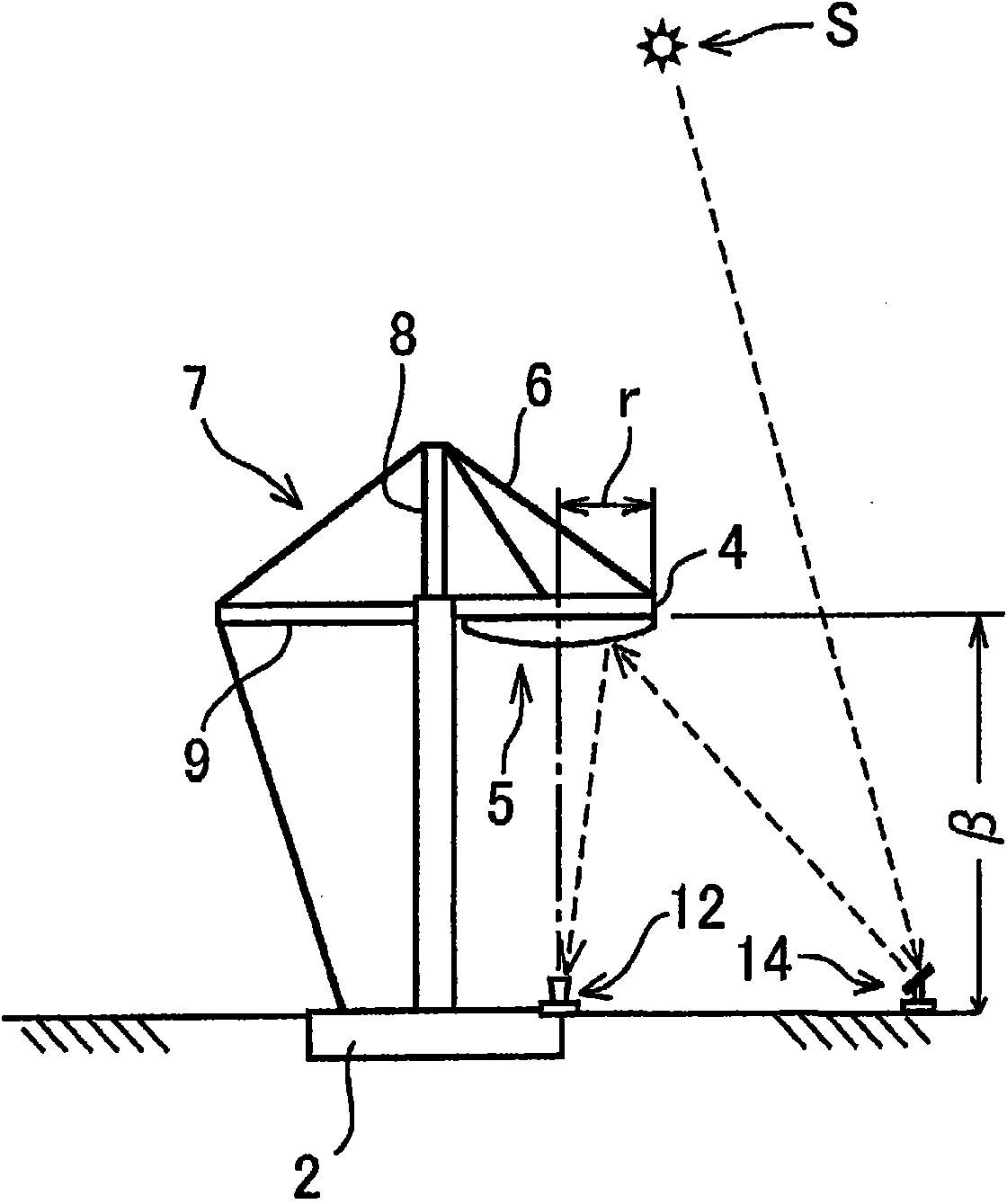
[0055] Such as figure 1 As shown, in the solar thermal power generation device A, a central reflector 5 is installed in a cantilevered manner on one side of the erected pillar 1, and a tower door 8 is erected on the top of the pillar 5. The above-mentioned central reflector 5 is fixed by the brace material 7, and the above-mentioned pillar 1 is supported by connecting the above-mentioned pylon 8 and the protruding material 9 protruding on the back side of the above-mentioned pillar 1 and the brace material 7 of the base 2.

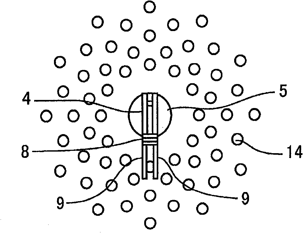
[0056] Furthermore, if figure 2 As shown, many heliostats 14 are concentrically arranged around the pillar 1 on which the central reflector 5 is mounted in a cantilever shape, and are arranged so that the north side of the pillar 1 is denser than the south side of the pillar 1 .

[0057] In the solar thermal power generation device A constituted in this way, many heliostats 14 reflect sunlight, and the reflected light is reflected on the central reflect...

Embodiment 2

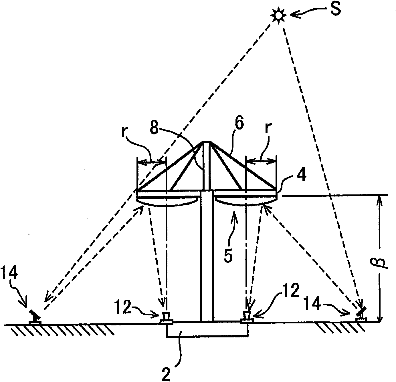
[0060] In the solar thermal power generation device A of this embodiment, if image 3 and Figure 4 As shown, two central reflectors 5, 5 are provided on the central pillar 1. As shown in FIG. Specifically, such as Figure 4 As shown, it is equipped with: a plurality of heliostats 14 that reflect sunlight; central reflectors 5, 5 that condense the reflected light reflected by the heliostats 14 to the heat medium heating units 12, 12; and A steam turbine power generation unit in which the heat medium heated by the above-mentioned heating unit 12 serves as a heat source. Furthermore, the above-mentioned center reflectors 5, 5 are provided in a cantilever shape on both sides of the above-mentioned pillar 1. As shown in FIG.

[0061] In addition, the said heliostats 5, 5 are installed so that the north side of a pillar may become denser than the south side of a pillar, and the reflection efficiency of sunlight may be improved.


PUM


Abstract

This object aims to provide a center reflector support device configured to improve setting density of heliostats, to reduce the blocking or shadowing of reflection light from the heliostats, and to stably and firmly support a central reflector. In a beam down system solar generation device, the center reflector is fixed on one side of a standing post in a cantilever fashion, a pylon is stood at the top of the post, the center reflector is fixed by a stay member set at the pylon, and the post is supported by a stay member to connect the pylon and a jut jutting out into the back side of the post with a base.

Description

technical field [0001] The present invention relates to a beam down system solar thermal power generation device, which reduces blocking or shadowing of reflected light from heliostats while increasing the installation density of heliostats, thereby stabilizing And firmly support the solar thermal power generation device of the central reflector. Background technique [0002] In recent years, interest in the global environment such as air pollution due to exhaust gas from combustion of fossil fuels and depletion of fossil fuels has increased, and alternative energy sources instead of the above-mentioned fossil fuels have attracted attention. As such alternative energy sources, wind power generation and solar power generation are gaining popularity. [0003] In particular, heat the heat medium with the heat of concentrated sunlight, generate water vapor through the heat of the heat medium, and drive the steam turbine to generate electricity through the water vapor. It is at...

Claims


Application Information

Patent Timeline
Patent Type & Authority Applications(China)
IPC IPC(8): F03G6/00F03G6/06F24J2/18F24J2/46F24J2/52G02B5/10G02B7/182F24S20/20F24S20/30F24S23/70F24S23/77F24S23/79F24S90/00
CPCY02E10/46F24J2/4649F24J2002/1076Y02E10/41G02B7/183F24J2/18F24J2/523F24J2/07F03G6/065Y02E10/47F24S80/20F24S23/79F24S20/20F24S25/10F24S2023/87F24S25/00F24S23/70Y02E10/40
Inventor 江泽一明井上浩男川口隆滨田让
Owner MITSUI ENG & SHIPBUILD CO LTD
Why Eureka
Try Eureka