High-blast-temperature hot-blast stove burnt in convection swirling heat storage medium

A heat storage medium and hot blast stove technology, applied in brick blast furnaces, etc., can solve problems such as waste of energy, complex structure, insufficient combustion, etc., and achieve the effect of increasing the temperature of hot blast, improving heat transfer effect, and simple structure

Inactive Publication Date: 2010-12-08
ZHENGZHOU YUXING REFRACTORY MATERIAL
View PDF4 Cites 12 Cited by
  • Summary
  • Abstract
  • Description
  • Claims
  • Application Information

AI Technical Summary

Problems solved by technology

[0004] In view of the above situation, in order to overcome the defects of the prior art, the object of the present invention is to propose a novel hot blast stove with a simple structure and no space for the combustion chamber, which is called a high-temperature hot air stove for combustion in a counter-swirling heat storage medium. The hot blast stove effectively solves the problems of complex structure, uneven gas mixing, insufficient combustion, environmental pollution, and waste of energy. The technical solution is that the overall shape of the hot blast stove is bowl-shaped, including the upper pre-combustion chamber , the conical combustion chamber (2), which together form a space in which the airflow can rotate, mix, and burn; the gas inlet pipe (7) and the air inlet pipe perpendicular to the axis of the hot blast stove are symmetrically arranged on the wall of the pre-combustion chamber (1) (8), a hot blast outlet pipe (9) coaxial with the hot blast stove is installed on the dome of the pre-combustion chamber (1); the gas inlet pipe (7) and the air inlet pipe (8) are formed by a circular shape before entering the pre-combus

Method used


Image

  • High-blast-temperature hot-blast stove burnt in convection swirling heat storage medium
  • High-blast-temperature hot-blast stove burnt in convection swirling heat storage medium
  • High-blast-temperature hot-blast stove burnt in convection swirling heat storage medium

Examples


Embodiment Construction

[0008] The specific implementation manners of the present invention will be described in detail below in conjunction with the accompanying drawings.

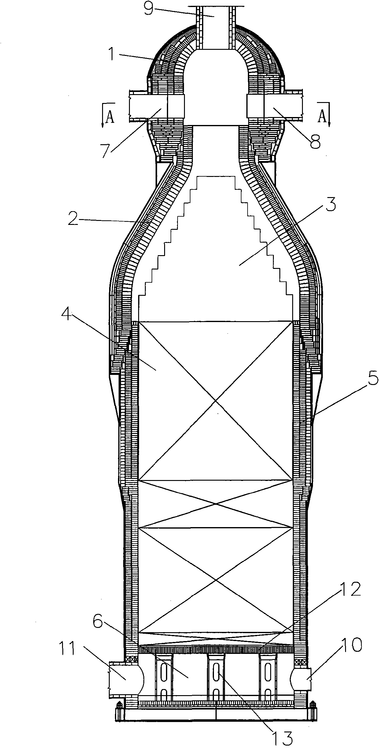
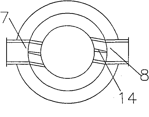
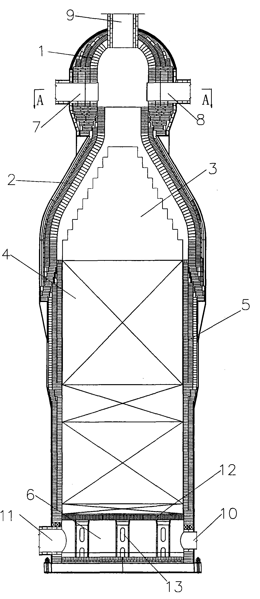
[0009] Depend on figure 1 , 2 Shown, the present invention is, in the steel casing, is formed by masonry by the refractory material of different specification, and it is formed by pre-combustion chamber (1), the porous regenerator ( 3), the regenerator (5) and the regenerator (4) stacked with checker bricks in it, and the cold air chamber (6) together constitute the overall structure of the hot blast stove. The pre-combustion chamber (1) and its The lower conical combustors (2) are connected by a labyrinth without stress, and the conical combustors (2) are fully filled with porous regenerators (3), which together form a gas flow that can rotate and mix in it. , the combustion device of combustion, on the vertical wall body of pre-combustion chamber (1), the gas intake pipe (7) and the air intake pipe (8) of vertical hot blast ...


PUM


Abstract

The invention relates to a high-blast-temperature hot-blast stove burnt in a convection swirling heat storage medium, effectively solving the problems of complicated structure, non-uniform gas mixing, insufficient burning, environmental pollution and energy waste. The stove adopts the structure that a pre-burning chamber of a bell jar on the top of a ball and a taper-section barrel-shaped burning chamber below the pre-burning chamber are connected by using a labyrinth without stress action; the taper-section burning chamber is sufficiently filled with porous heat storage bodies; a coal gas inlet pipe and an air inlet pipe are distributed on the vertical wall of the pre-burning chamber; a barrel-shaped heat storage chamber is arranged below the burning chamber, and checker brick heat storage bodies are stacked on grates in the heat storage chamber; a cold air chamber is arranged below the heat storage chamber, and a smoke exhaust pipe and a cold air inlet pipe are connected to the wall; the grates for holding the heat storage bodies are mutually spaced with expansion gaps, put on a beam and supported by grate supporting posts; the supporting posts are fixed on a rigid base of the hot-blast furnace; and a central vault line of the pre-burning chamber is provided with a hot-blast outlet pipe coaxial with the hot-blast furnace. The invention has the advantages of simple structure, high mixed burning intensity, good air flow heat exchange effect and raised hot-blast temperature.

Description

1. Technical field [0001] The invention relates to a hot blast stove, especially as a kind of equipment that provides high-temperature and high-pressure blast for ironmaking blast furnaces, or provides hot blast for general industrial heating, and is a high-blast-temperature hot-blast stove that burns in a counter-swirl heat storage medium. . 2. Background technology [0002] At present, blast furnace hot blast stoves have entered the era of top-fired hot blast stoves. From the perspective of energy saving and consumption reduction, blast furnace blasts are required to develop in the direction of high blast temperature, especially when burning low calorific value blast furnace gas to obtain high hot blast temperatures, and must reach a certain level. Thermal efficiency, and ultimately achieve the goals of high efficiency, energy saving, environmental protection, and increased production. To achieve high efficiency and high air temperature for a hot blast stove, the key lies...

Claims


Application Information

Patent Timeline
IPC IPC(8): C21B9/02
Inventor 刘世聚陈维汉刘东崔方辉
Owner ZHENGZHOU YUXING REFRACTORY MATERIAL
Why Eureka
Try Eureka