Winding change-over switch of three-phase AC motor

A three-phase AC and winding switching technology, which is applied in the direction of AC motor control, electromechanical transmission control, motor generator control, etc., can solve the problems of instantaneous current switching, induced voltage rise, overcurrent, etc., and prevent abnormal operation and device damage

Active Publication Date: 2010-12-08
YASKAWA DENKI KK
View PDF1 Cites 18 Cited by
  • Summary
  • Abstract
  • Description
  • Claims
  • Application Information

AI Technical Summary

Problems solved by technology

Therefore, the sinusoidal current flowing in the full-wave rectifier 113 and the semiconductor switch 114 is disturbed.
Moreover, a current flows through the resistor 125 constituting the snubber circuit, causing the sine wave current to be disturbed
[0009] In this way, there is the following problem: when the motor winding changes from the excitation state to the non-excitation state, the energy accumulated in the inductance of the motor winding is released, so the current switching cannot be performed instantaneously, and the motor current that should be a sine wave is disturbed.
However, when assembling components, if the high-speed side control signal is wired to the low-speed side and the low-speed side cont

Method used


Image

  • Winding change-over switch of three-phase AC motor
  • Winding change-over switch of three-phase AC motor
  • Winding change-over switch of three-phase AC motor

Examples


Embodiment 1

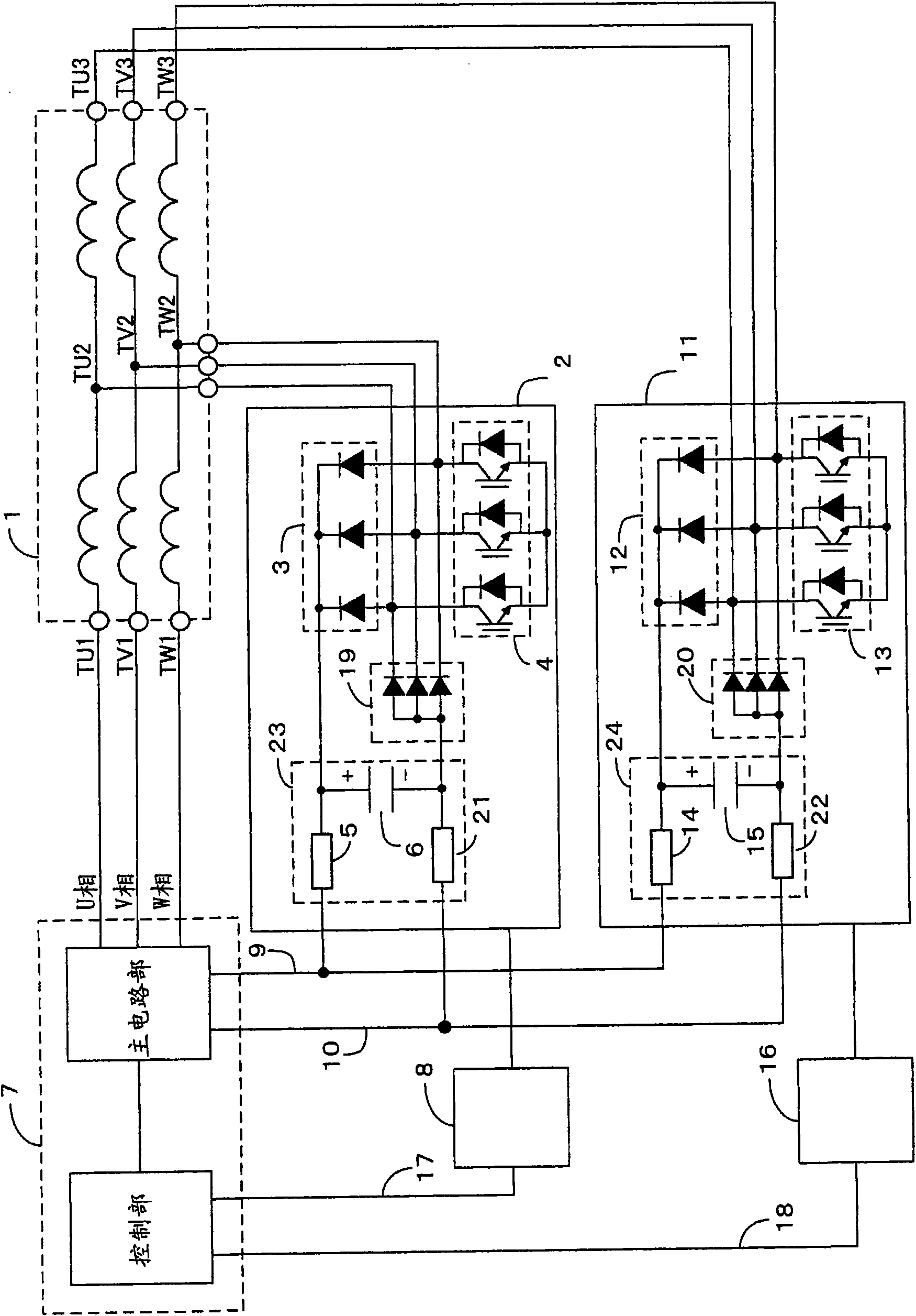
[0032] figure 1 It is a figure which shows the 1st Example of the winding switching device of the three-phase AC motor of this invention. exist figure 1 Among them, 1 is a three-phase AC motor, 2 and 11 are winding switching parts, 3 and 12 are diode parts, 4 and 13 are switching parts, 5 and 14 are positive charging resistors, 6 and 15 are capacitors, and 7 is reverse 8 and 16 are drive circuits, 9 is a DC positive side bus, 10 is a DC negative side bus, 17 and 18 are drive signals, 21 and 22 are negative side charging resistors, and 23 and 24 are potential fixing parts.

[0033] The inverter 7 is composed of a control unit and a main circuit.

[0034] For the three-phase AC motor 1, one center tap (TU2, TV2, TW2) for each phase winding, winding start terminal (TU1, TV1, TW1) and winding end terminal for each phase winding are provided outside the motor. Terminals (TU3, TV3, TW3).

[0035] The winding start terminals (TU1, TV1, TW1) of the windings of each phase of the ...

Embodiment 2

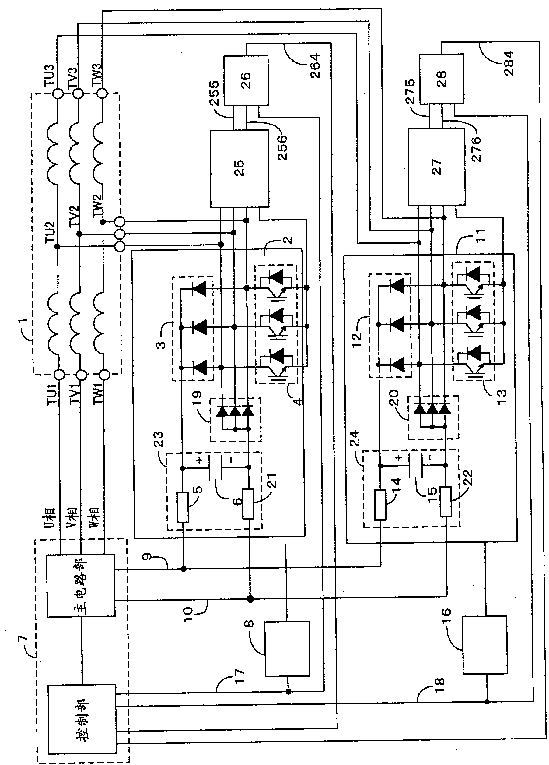
[0094] image 3 It is a figure which shows the 2nd Example of the winding switching device of the three-phase AC motor of this invention. exist image 3 Among them, 25 and 27 are state detectors, 26 and 28 are comparators, 255 and 275 are winding switching part on-state signals, 256 and 276 are * Winding switching unit off-state signal, 264 and 284 are winding switching unit abnormal signals.

[0095] The difference from Embodiment 1 is that, in this embodiment, there are: a state detector, which detects the conduction state of each power semiconductor switching element constituting the switch portion in the winding switching portion; a comparator, which detects the conduction state according to the state. The detection result of the inverter and the drive signal output from the control unit of the inverter are used to detect the abnormality of the winding switching unit.

[0096] First, an outline of the operation of the state detector and the comparator will be described....


PUM


Abstract

A winding change-over switch of a three-phase AC motor which can switch the motor current quickly while minimizing disturbance of a sine wave current and can prevent an abnormal operation or the destruction of an apparatus by detecting wrong wiring or abnormality of a component. A winding change-over section ((2(11)) connects a positive-side charging resistor (5(14)), a negative-side charging resistor (21(22)) and a capacitor (6(15)) in series between the DC positive-side bus (9) and the DC negative-side bus (10) of an inverter (7), connects the positive side of the capacitor with the cathode of a diode portion (3(12)) and then changes over a high-speed winding to from a low-speed winding under such a state that the potential of the capacitor is equalized to the DC bus voltage of the inverter. In addition, wrong wiring or abnormality of a component is detected by means of a state detector (25(27)) and a comparator (26(28)).

Description

technical field [0001] The invention relates to a winding switching device of a three-phase AC motor that expands the speed control range by switching the windings of the three-phase AC motor, and is aimed at the industrial fields including vehicle drive, machine tool spindle drive and servo devices. Background technique [0002] In inverter-driven machine tool spindles and vehicle drive devices, a winding switching method is adopted as a means of obtaining a sufficiently large torque in a low-speed range while realizing operation in a high-speed range (for example, refer to Patent Document 1) . [0003] Figure 5 It is a diagram showing an example of a conventional winding switching device for a three-phase AC motor. according to Figure 5 , the existing winding switching device will be described. [0004] For the three-phase AC motor 111, outside the motor, there are center taps (TU2, TV2, TW2) of each phase winding, winding start terminals and winding end terminals of e...

Claims


Application Information

Patent Timeline
IPC IPC(8): H02P27/06H02P21/04H02P23/03H02P23/07
CPCH02P25/20
Inventor 东川康儿山田健二山中克利
Owner YASKAWA DENKI KK
Why Eureka
Try Eureka